
 Here at Hackaday, we pride ourselves on bringing you the very freshest of hacks. But that doesn’t mean we catch all the good stuff the first time around, and occasionally we get a tip on an older project that really should have been covered the first time around. This remarkable circuit sculpture clock is a perfect example of one that almost got away.
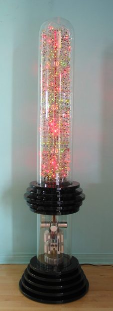
[Gislain Benoit] creation is called “The Tower” for good reason: it’s built inside what amounts to a giant glass test tube. Inverted and adorned with MDF discs, the Pyrex tube stands 5 feet (1.5 meters) tall, and is absolutely stuffed with electronic goodness. There are more than 2,100 discrete components mounted inside on a helical framework of carefully bent wires, forming a vertical sculpture that displays the time on three separate pairs of seven-segment displays. All the diode-transitor logic circuits are built from discrete components; nary a chip was used, and to spice things up, [Gislain] used LEDs in place of regular diodes everywhere in the circuit. The result is a constant light show as the clock goes through its paces.
The whole thing looks amazing, and even the power supply at the base works in the overall presentation. The design is a bit of a departure from [Gislain]’s previous circuit sculpture clock, but it’s just as beautiful, and equally as mind-boggling in terms of construction difficulty.
Thanks to [Maarten] for the belated tip on this one.


This looks stunning, I wish I could see a video!
Yeah, and it appears that one needs to “find” the clock digits among all those other lights.
If you can picture the circuit operating in your minds eye, there are multiple ripple counters, the highest frequency would probably be at the bottom going down in frequency as you progress up the tower with the lowest frequency at the top. And they are using LED’s in the discrete logic flip-flops instead of traditional diodes so that you can see the state of the flip flop.
I’m also guessing that the lower two 7 segments digits are the seconds, the middle two 7 segments are the minutes and the two 7 segments near the top are the hours.
So multiple flip-flop ripple counters and binary to decimal encoders would be the bulk of the circuit. And at the top looks like they have some special circuitry that they might be doing something interesting every hour on the hour.
I suspect that they would use 2^4 with a reset on 10 ripple counter followed by a 2^3 with a reset on 6 ripple instead of a 2^6 with a reset on 60 ripple counter just so that more ripple counter circuitry could be used, and less decoding logic (binary to decimal encoders) which would not necessarily be as visually appealing.
So anyhow, as the different parts of the clock would only change their lighting as the ripple rises up the tower, I do not think that it would be difficult to locate the six mostly static 7 segment displays, but since it is more a piece of art that happens to be a clock I do not think that it is all that important.
Oh, my! I love it, especially “LED–transistor” logic! That idea, visible diodes, should be part of every course in electronics. It’s a wonderful example of “thinking out of the box”, but not far away from the box.
This clock is a refinement of a type of construction that has been called “air chassis”, just about always a very temporary circuit, supported only by the stiffness of component leads.
Around 1965 or so, I made myself a small bunch of battery–powered discrete–component DTL, one gate per small perf. board. Used 6977 (iirc) indicator tubes and a bounceless pushbutton. Quite successful.
Proof that off planet aliens live amongst us. And don’t wear a watch.
Truly beautifu l and cood… On the other hand I really do not want to pay his electric bill!
Whole thing probably uses a handful of watts max
The creator estimates consumption to be 36W,
Leds are individually cheap in power drawing 20mA tops, but when you got over 1400 Leds all blinking they start to add up fast.