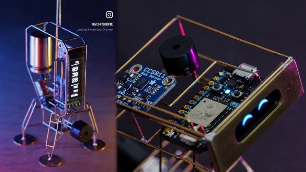
Well, this might just be a Hackaday first. Certainly not the circuit sculpture part, nor the wearable aspect, but the glorious combination of the two. Behold [CMoz]’s Fashionably on Task: a Smart Bracelet for Forgetfulness. The name may be long, but the intent is concise: to showcase your top five must-dos for the day.
This lovely bracelet uses a tri-color e-paper display, and it’s WiFi enabled in order to receive input from the corresponding phone app. Although the cute pink ESP32-C3 is programmed in PlatformIO, the code will work with the Arduino IDE as well.
To get down to business, just power on the bracelet. If it can’t connect to the network you’ve hard-coded, it will broadcast it’s own access point. Connect with your phone to the custom web page, and Bob’s your uncle. From here, you can enter the tasks, change the colors around, mark tasks as complete, and remove tasks or reset recurring reminders.
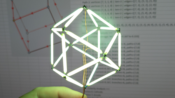
The nifty part is that e-paper screen, since it will of course continue to display your list once powered down. Here’s the full code. Then you can deep-dive into the graph theory of circuit sculptures.