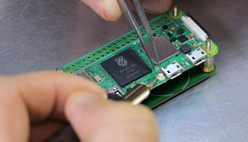
We’ve only started to tap into the potential of the brand new Pi Zero 2. Having finally received his board, [Brian Dorey] shows us how to boost your Pi’s WiFi, the hacker way. Inline with the onboard WiFi antenna can be found a u.FL footprint, and you just know that someone had to add an external antenna. This is where [Brian] comes in, with a photo-rich writeup and video tutorial, embedded below, that will have you modify your own Zero in no time. His measurements show seeing fourteen networks available in a spot where he’d only see four before, and the RSSI levels reported have improved by 5 dB -10 dB, big when it comes to getting a further or more stable connection.
With old laptops being a decent source of WiFi antennas, you only need to procure a u.FL connector and practice soldering a bit before you take this on! The hardest part of such a project tends to be not accidentally putting any solder on the u.FL connector’s metal can – and [Brian] mostly succeeds in that! He shows how to disconnect the external antenna to avoid signal reflections and the like, and, of course, you will be expected to never power your Pi Zero on without an attached antenna afterwards, lest you have your transmitter become fatally confused by the mismatch of hardware-defined impedance expectations. A Pi Zero isn’t the only place where you’ll encounter footprints for connectors you can add, and arguably, that’s your duty as a hacker – modifying the things you work with in a way that adds functionality. Don’t forget to share how you did it!
This trick should be pretty helpful if you’re ever to put your new Pi Zero in a full-metal enclosure. Curious about the Raspberry Pi antenna’s inner workings? We’ve covered them before! If you’d like to see some previous Raspberry Pi mods, here’s one for the Pi 3, and here’s one for the original Zero W – from [Brian], too!


The article shows it with a short u.FL to SMA cable and an SMA antenna. That antenna was probably harvested from an old desktop wireless router, not a laptop; many of them have antennas that can be unscrewed from the SMA connector on the router and reused. That type of antenna has gain expressed in positive rather than negative (loss) numbers.
Partly that comes from the antenna being large enough to not have impedance matching losses, which is always a net win. But remember that gain isn’t magic and more isn’t always better. The larger antenna has a doughnut-shaped signal pattern, with the nulls (directions where the least signal goes) pointing off the ends of the antenna (typically straight up and down). If the directions where the nulls point are areas you want to cover, the gain antenna will be worse then the basically non-directional one on the circuit board.
Not all, but most older laptops do use the u.FL connector onboard. They usually don’t use the u.FL to SMA, although some do. Most use the u.FL connector to connect directly to the antenna that’s usually around the display. I have a bunch of computers here that use laptop style mainboards with addon cards plugged into the mainboard that have the u.FL connector on it. I use the same network cards in some laptops. In this case, they even use the u.FL to SMA cable and SMA antenna’s which is great for me as I intend to rip them out.
“the gain antenna will be worse then the basically non-directional one on the circuit board.”
What in the world makes you think that antenna’s non-directional?? Of course it’s directional – just look at it. There are nulls in the Pi Zero 2’s antenna, too ( https://www.embeddedcomputing.com/technology/analog-and-power/power-semiconductors-wireless-charging/a-lesson-in-wireless-engineering-from-the-raspberry-pi ). Basically anything coming from the far side (opposite the antenna) is down 5 to 10 dB, and there are 20 dB nulls there, too.
But for indoor use, this is completely pointless, because if the line-of-sight’s in a null, there will be plenty of reflections that aren’t.
Less directional antenna then? Some types of antennas have sharper nulls than others. My point is that more isn’t ALWAYS better, though it is more often than not.
“Some types of antennas have sharper nulls than others.”
Yes. Sure. There’s a single direction where this antenna *theoretically* has a null that’s probably 40 dB lower than its peak, and there probably isn’t that deep a null in the embedded one.
Except you’re never going to see that 40 dB null in real life, because there’ll be reflections that put you out of the ~few square degrees that the null covers. Comparing the “theoretical” null of the antenna (in a range or anechoic chamber) to the actual nulls of the embedded antenna isn’t a fair comparison, because the embedded antenna’s getting the benefit of reflections (it’s not being tested on its own) and the whip antenna isn’t.
Watching the video, it seems a little haphazard to cut the trace – especially when there’s a resistor not far along. I wouldn’t be surprised if you could just move it.
That how it’s done on the original pi zero. I’m a bit surprised he did it this way. He even wrote an article a while ago how to do this exact thing. The way the antenna works is different on the new version compared to the old system. I hope to fool around with it, but considering the old ones are always hard to come by, I don’t expect to be able to buy a bunch of em in the future.
https://www.briandorey.com/post/raspberry-pi-zero-w-external-antenna-mod
Yeah that’s likely to be the case since fcc and similar testing often requires fitting an external antenna.
“especially when there’s a resistor not far along. ”
This is mentioned in the linked article. It’s not a resistor – it’s the coupling cap at the feed point. It’s 4.33 mm from the U.FL connector: leaving it open would leave you a stub. He calculated it as 17 GHz, but that was for open space – it’d be more like 12 GHz assuming about a 70% velocity factor on the PCB since it looks like coplanar waveguide.
To me it’d be interesting to test if it were left open, because that distance is curiously close to exactly a 5th harmonic of 2.4 GHz.
I’ve watched the video and pictures, and also checked on my own Zero W 2 when I received it – there’s no resistor you could move on the Zero W 2 (the new model), so you’re forced to cut the trace to disconnect the original antenna.
> If the directions where the nulls point are areas you want to cover, the gain antenna will be worse then the basically non-directional one on the circuit board.
There’s no such thing as a non-directional antenna (damn hairy ball theorem!). The PCB antenna has nulls too; it’s just a lot less obvious where they are unless you have a radiation pattern to look at.
“There’s no such thing as a non-directional antenna”
No such thing as a single non-directional antenna. Obviously you can create a virtual non-directional antenna pretty easily with coverage from multiple antennas.
” it’s just a lot less obvious where they are unless you have a radiation pattern to look at.”
It’s usually pretty easy to understand the radiation pattern just from geometry, at least to first order. The Pi Zero’s antenna is a resonant cavity: so it’s a “gap” (close to the edge of the PCB) where the feed point is, then a trapezoidal cavity that’s grounded at the back (to act like a mirror to ‘trap’ everything incident).
Obviously there’s one direction here that’s terrible, which is if you’re staring at the back of the cavity (so you only see the “wall” of the mirror), and the worst nulls are usually just slightly off from the back lobe where you get reflections that cause further interference.
The Zero 2’s antenna is slightly modified from the original Zero (based on the 3B) but geometrically it’s basically the same.
The closest thing to a true omnidirectional antenna is an antenna that is much, much shorter than resonant length for the desired wavelength. A tiny little doublet that’s 2cm long will be very close to omnidirectional for 80m waves. It would also necessarily be horribly inefficient.
Running a WiFi chip like this without antenna is almost always not a problem. I’m not sure if you can really do it indefinitely, but several hours doesn’t seem to cause any problems. I would expect so for a consumer product…
This could be illegal.
I think with all these “hack an antenna onto a license-free radio device” articles it might be nice to warn people that they could be violating the laws of their country when they do it. I’m not saying tell people “no, never do this”. I’m not saying anyone is very likely to get into trouble. It’s just that I’ve seen enough dumb internet-comment arguments to know that we do have a lot of people here who don’t understand how antenna gain affects ERP limits and how they could (although probably won’t) receive a fine or other punishment. Again, I’m not saying “Don’t do this” I’m saying “Know this”. Do what you will with the knowledge.
I’m speaking of the laws here in the US but I bet most other countries work similarly. License free radio such as WiFi, Bluetooth and pretty much everything else we see here that is wireless (except amateur radio) are governed under Part15. Part15 sets power limits in ERP, “Effective Radiated Power”, not the absolute number of watts going into the antenna. What this means is if your antenna focusses more power in one direction you have to measure how much power it is focussing into that direction. It doesn’t matter if the overall total amount of radiated power radiated in all directions is unchanged. When an antenna adds gain it is focussing more of it’s power in a limited number of directions. You can take a perfectly legal part 15 device and make it illegal just by adding a better antenna.
Again, I’m not saying Don’t Do This Ever! I’m just saying it’s good to be aware. Compare it to driving on the expressway. In most areas traffic regularly flows faster than the posted speed limit. But even when one is driving along with traffic wouldn’t they rather know they are doing 5 over as they pass the traffic cop rather than be ignorant of it?
I think most hackaday articles are suggesting to do something that’s either illegal or immoral or cancer-causing or in bad taste, perhaps it’s best for people to sort out their own issues to avoid death or arrest or embarrassment. If you give out legal advice you should be prepared to be sued by people who are paying attention to you.
“This could be illegal.”
I guess that is why the word “unapproved” is in the Title…
It’s unlikely that putting an antenna from a wireless router on the Raspberry Pi will violate ERP limits on the 2.4 GHz band. The onboard radio is almost certainly a lower power one than the one in the router because of power constraints on the Pi.
A more serious concern is that a change to the board, especially adding a significant antenna surface, might make it noncompliant with the limits on unintentional radiators. In other words, adding that antenna might increase its emission levels on other frequencies (NOT the 2.4 GHz WiFi band) beyond acceptable levels, because other signals on the board could couple with the antenna and be radiated.
Any computer is an unintentional radiator because all those high speed electrical signals can cause radio interference. A computer with any form of wireless interface is both an intentional and unintentional radiator and has to comply with two sets of rules.
‘Splain it to me Lucy: How does “gain” equal “radiation”?
Interesting aside: “dead” Pi Zero here has a working WiFi/BT chip and regulator.
I wonder if its possible to remove the broken BCM, and hook up the chip with some mod wire?
Would then effectively be able to switch between two different antennas of opposite directions in a cantenna to use it as a relay.
Wiring the chip up to something would not be impossible! We don’t have schematics, but it’s basically SDIO for WiFi, UART for Bluetooth and then some control signals (pinout for all of these found in Device Tree definitions). However, the “relay” part of it, I’m doubtful you could pull it off without a CPU, and whether it’d be possible to have a single chipset do a AP+client while doing an antenna switch like that. Either way, once you have some interesting research going, send it to us ;-P
It has been done for the RPi4 too.
https://community.element14.com/members-area/personalblogs/b/blog/posts/molex-antenna-adventures-starring-a-rpi4
Instead of using a u.fl male, there are female sockets of a similar footprint (e.g. Murata make them) that incorporate a switch. So when you remove the plugged-in connector, the connection is remade back to the on-board antenna.
Yes, but then you’d have to get the equipment needed to install the corresponding connector onto the cable, and that won’t be cheap! If you go with the standard, you can get already made cables easily.
u.fl is so tiny. My meat hands do not comply to working with the little things.
Is there anything else that’s a little less wreckable? Thos contacts on the connector l=just love to mash and break off.
vr Wreck-It-Ralph