We’re no strangers to [Ivan]’s work and this time he’s building a relatively small CNC machine using extrusion, 3D printed parts, and a Makita router. The plans are available at a small cost, but just watching the accelerated build is fascinating.
You might think you could just attach something to an existing 3D printer frame that cuts like a Dremel tool. You can do that, but for most purposes, you need something stiffer than most desktop printers. You can see how solid this build is with multiple extrusions forming the base and very rigid axes.
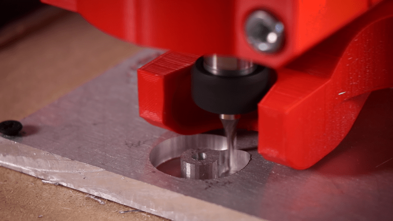
Judging from the video, the machine made short work of some aluminum plate. Of course, some of that is in the choice of tool, but it appears the machine is stable enough to hold the workpiece and the tool stable to allow this sort of service. [Ivan] says the machine cost him about 600 Euro ($670 USD) and you need a printer that can create parts as large as 180 x 180 mm.
There are quite a few similar mostly 3D printed machines on Thingiverse, including some that have been through multiple versions. If you have an old 3D printer sitting around for parts, you may have nearly everything you need if you add some printed parts, presumably from your new printer.
We’ve seen plenty of CNC builds if you want to pick and choose your own design. Depending on your expectations, it doesn’t have to be an expensive project.


“Judging from the video, the machine made short work of some aluminum plate.”
Euhm, not really.
I’m guessing that machine was making lots of noise for more then an hour to get that part made out of aluminum. Just look at the very shallow cuts for each pass an the number of passes needed to get through the aluminum. Speeding up the video and also cutting out large parts of the “boring noise in between” only partially hides that fact.
This machine may be adequate for some light wood routing, but if you want any decent cutting speed in aluminum then start with lineair rails that are supported over the whole length, and also ditch the long timing belts along the rails. A decent CNC machine would have made that part in a few minutes.
Those round unsupported rails are just not a good fit for any CNC machine.
I really do not understand why people still use them.
Just do a price / stiffness comparison with the MGN rails (12 or 15mm) These have holes to bolt them down every few cm and their load numbers are already quite adequate for a machine like this. There is no need to go to the (much more expensive) HGR rails for such a small machine.
Remember that load rating of linear rail are only valid if they are properly mounted on a (infinite) stiff support.
A MGN rail mounted on aluminum channel will have a very low load rating (ie 3d printer).
There are indeed plenty of other considerations, and you always have to take the complete design into consideration, but at least you have a chance to makes something decent with such guides.
MGN12C (the short bearing blocks) from Hiwin have a dynamic load rating of 290kgf, so you can loose some of that and still have something decent. (The MGN15H version (wider and longer bearing blocks) even has a dynamic load rating of 650kgf. The wider rails also helps a bit with having more support on such aluminum channels)
A much bigger problem probably is that these rails need to be aligned properly to within 20micrometer.
Another important aspect is that that is the load rating of a Hiwin rails.
In China there are many small and nameless factories, which all make products that look the same but can vary a lot in quality.
With such bearings (and also ball spindles and other parts) it’s often a good idea to take the new product apart, wash the grinding grit out of them and assemble and oil them properly before you start using them.
There are probably more factors which can drastically reduce the life expectancy of such rails. To make something proper, you have to get all the details right. One of those details can be to not make your construction too stiff, so does have a bit of compliance as a safety net for mouning errors.
I also liked the Cetus 3D (printer) a lot. I even almost bought it.
It’s not an ideal printer, but at least with the lineair rails you have better mechanical starting point to improve upon than with many other printers. For such a printer load rating is irellevant. It’s more about a straight precise and smooth motion.
I have a Cetus and it’s been an astoundingly good printer, especially for the price. The whole selling point for me over the competition at the time was the linear rails and I’m so glad I went with my intuition based on that.
Dead nuts reliable, bed has stayed fixed and level since I installed it, it runs quiet and smooth and puts out great prints. The only thing about it I can fault is that the stepper driver for the extruder isn’t replaceable and mine fried after 2 years of service when the wire loom to the extruder came loose mid print, requiring a new motherboard.
It would also have been nice if it was easier to use third-party slicers with it, but UPstudio is actually ok for most purposes and if you just absolutely *have* to do something outside of the parameters available in UPstudio it’s not terribly hard.
Even the factory ‘gummy’ bed has been excellent and still works as good as out of the box years later. I upgraded to the heated bed, but truth be told only use it for very large prints that I know will warp.
and did you see those vibrations? the entire router almost fell off the table in his video moving quite a few centimeters just because it was not bolted to anything….
Exactly. The rails are the problem here clearly. And the belts. Not the 3d printed parts, no. Those are stiff as on a 5 ton composite granite machine.
You missed the point of this whole build. You can’t be further from it even if you try.
Yeah, it’s a 3-axis machine built from pretty affordable and accessible COTS parts, along with some 3D printed stuff. As much as I love a giant honkin knee mill, this will give you access to middling quality aluminum parts, and could easily be bootstrappable if you wanted to increase stiffness.
I 2nd that, even modern 3D printers use only MGN rails, Voron 0.1 MGN7, Trident MGN12 for X and MGN9 for Z/Y, and so on. Only the Legacy Voron used rods for whoever has leftover and want to decent printer.
For almost $700USD I’d rather buy something that’s many times more rigid and doesn’t hold together with 3D printed plastic parts. You can get a ShapeOko clone on Amazon for $700 with a 300w spindle and a 400×400 work area. This is just silly.
Lately I’ve seen a blue 3040 for around EUR 1000 or a 4060 for around EUR1200 on aliexrpess / chine and it looks like it could actually be decent. It is not for me though, I am more into building my own machine from separate parts to the specifications that I want.
I would like to see DIY CNCs that are capable of complex or precise movements rather than just cutting a 2D shape that could be done by hand (albeit slowly).
I did watch the build and appreciate his efforts but anyone know of a diy CNC that can do 3D relief milling or thread milling?
If it can do a 2D shape it can do the 3d relief, any many other possible results – as that is entirely down to what the file you send it is telling it to do (assuming what you want is possible for a 3 axis machine of this small working area).
Something this pathetic is going to need a very very gentle small cuts – peck the part to death to get anything like a good surface finish, so its going to take quite a while do do, but within its x-y-z envelope, and with the right cutting bit(s) it can technically do it.
if you really want to mill threads implying a single point cutting tool being run through a spiral over running a tap into it I suspect this machine won’t really be stiff enough, and for that you really need a stepper/servo motor on the spindle – that sort of threading operation is much more natural on a lathe, on a 3 axis machine you will need to be able to rotate the tool and hold it at the correct angle as the circle you are threading is traced by the other axis.
Nope.
Thread milling is quite easy. The mill itself just cuts a 60 degree (for metric thread) groove in whatever it encounters. So you just have to generate a spiral tool path.
The mill itself is also long and narrow (An M6 thread mill has to be smaller then 5mm at it’s widest point, and therefore the shaft must be 4mm or less.) The result is that you have to be careful with these mills, and it also means you do not need much stiffness from the machine itself. (But you do need accurate positioning, no backlash, that sort of thing)
The threads are usually also milled in 2 or three passes. and material removal is at a quite low rate.
I guess the reasons that you do not see many hobbyists do it is because of:
* Mills are relatively expensive.
* Mills are fragile, you have to be careful, (and with expensive mills, which is a scare factor).
* People are unfamiliar with the technique.
* Maybe just not many people need a lot of threaded holes to begin with (small numbers are easy to tap.
* It can only be done on CNC. Thread milling on a manual machine is… madness. (but theoretically still possible).
I am aware such things exist, but IMO you’re asking alot to spiral such an asymetrically loaded tool, that probably has heaps of stick out too on a machine that is not at all stiff either- hench the suggestion you just rotate the tool to the correct rake and scrape – no tool destroying doing it that way, its a constant very low tool load not a judggering chatter filled interrupted cutting mess that is bound to wreck the tool on this machine…
Yes the tool always being thin will need care on better machines, but on this I just can’t see it surviving as its the perfect storm of a delicate tool, a probably rather poor spindle, and very floppy machine – the axis registration is all on belts! almost certain to find a destructive resonance.
Much as I think Ivan is a great nutter, and maker this is IMO a nearly useless machine, even compared to many of his previous rather under spec machines… If it does what he needs it to as a speed he is happy with that is great, but on this machine design I can’t see any great redeeming feature that makes it worth the time and money of its creation, where most of his others the compromises at least made sense in light of his overall goal..
Thread milling can be done in 2 passes with the right tools. As for on a manual mill it’s all about the right gears in relation to the feed rod, it’s not hard just beyond the average Joe. I have been machinist since 80s and thread milling is nice for stainless and hard materials because taps often break in production. You can also thread mill on a 3 axis lathe ( live tooling)
Complex operations have nothing to do with the actual machine.. wanna get fancy? Get a better post-processor for your software. It’s all just G-code anyway..
There is a quite big distinction between “two and a half D” and 3D machining.
“Two and a half D” is (sort of) anything that can be made by a CNC machine that has three linear axis.
Both thread milling (as long as the holes are vertical) and 3D relief are part of that, and most portal routers can do that even when run completely run by open source software. It’s true that you do not see it often, but there are no severe technical complications. Thread milling may seem magic, but it is quite simple. In G-code it is just a spiral, which are a bunch of circles with some depth added. You do have to take care of the lead-in and lead-out, but it can even be manually written in G-code quite easily.
“3D” reliefs are also simple. For example bCNC has a leveling function that adds such a relief to the project at hand (for example PCB milling, which needs accurate depth).
For full 3D machining you need to add two rotating axes. The PocketNC https://pocketnc.com/ can do this. LinuxCNC also can control such machines. (LinuxCNC also has a layer for “custom axis transformations” For example it could also be a steward platform) The hard part is to generate the toolpaths. The “Path Workbench” in FreeCAD is under heavy development, but as far as I know it only supports generating paths for 3 linear axis as of yet. I am not aware of any open source software that can analyze a 3D object and generate a good toolpath for a 5-axis machine.
If you have a 5-axis machine (such as for example that PocketNC) Then it’s doable to manually write toolpaths for it as long as the object is relatively simple. For example for a V8 model engine you can just rotate the engine, and then machine pockets for a few of the cylinders (in 2.5D code) then rotate it and do the other cylinders.
I wonder how long it took to design the 3D printed parts… and how many iterations. He makes it look so simple, but there are lot’s of interesting challenges. Anyway, cool build!
Tiny? Well… it’s tiny compared to his last machine. Still bigger I bet than the ones a lot of us use.
There is no place like g28 x0y0z0
If whomever is having a good time, more power to him. If this brings him joy….stuff all the negative comments. I found it entertaining that he created something from bits collected and up-cycled. Whether it meets someone else’s standards is a moot point. Build what gets you through.