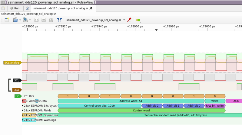
There’s a slew of hardware hacker problems that a logic analyzer is in a perfect position to solve. Whether you’re trying to understand why an SPI LCD screen doesn’t initialize, what’s up with your I2C bus, or determine the speed of an UART connection, you’ll really want to have a logic analyzer on hand. People have been using a Pi Pico as a logic analyzer in a pinch, and now [pico-coder] has shared a sigrok driver that adds proper support for a Pico to beloved tools like Pulseview.
The specs offered are impressive. Compared to the $10 “Saleae” clone analyzers we are so used to, this thing boasts 21 digital channels with up to 120 MHz capture speed, 3 ADC channels at up to 500 KHz, and hardware-based triggers. The GitHub repository linked above stores the driver files out-of-tree, but provides build instructions together with an easily flash-able uf2 firmware. It’s likely that you’ll soon see this driver in a stock Pulseview installation, however, given the submitter-friendly attitude we’ve witnessed on the sigrok mailing list. However, if you need a logic analyzer ASAP, you should follow the caringly offered quickstart guide.
We’ve covered Pulseview being used in combination with cheap accessible analyzers before — a must-watch if you need to get yourself up to speed on the value they provide to a hobbyist. If an oscilloscope is what you need and a smartphone is what you have, perhaps you’ll enjoy the Scoppy firmware for the Pico.
We thank [mip] for sharing this with us!


Cool, I have a pico banging around that I’ll probably utilize for this once it gets folded into Pulseview’s master tree.
One thing to keep in mind is the RP2040/Pi Pico does have a hardware bug (slightly mis-specced internal capacitances) that create ~9LSB non-linearity (0.22% of measurement range) at 4 points. Not a huge deal for most, but if you’re trying to debug some sensitive mixed-signal hardware with it, it’s something to be aware of.
Uhh…. Uhhhhhh…. 😬 I did NOT want to know what that pico is doing…
@fiddlingjunky said: “One thing to keep in mind is the RP2040/Pi Pico does have a hardware bug (slightly mis-specced internal capacitances) that create ~9LSB non-linearity (0.22% of measurement range) at 4 points.”
Yes, you are right. The ADC HW bug was discussed widely around February 2021. I assumed it was covered here on Hackaday, but when I searched through the RP2040 posts here I did not come up with anything. If you will excuse me, I’ll post some info and links here in my reply to your comment:
* Raspberry Pi confirms there is a hardware flaw in the RP2040 ADC. Refer to the RP2040 datasheet build-date: 2021-11-04, build-version: 150df05-clean, sections “4.9.3. ADC ENOB”, “4.9.4. INL and DNL”, and in-datasheet errata “RP2040-E11”.[1]
There are Differential Non-Linearities [2] and Integral Non-Linearities [3] caused by mis-matching of on-die ADC capacitors.
1. RP2040 Documentation and Datasheet
https://www.raspberrypi.com/documentation/microcontrollers/rp2040.html
https://datasheets.raspberrypi.com/rp2040/rp2040-datasheet.pdf
2. Differential Nonlinearity (DNL)
https://en.wikipedia.org/wiki/Differential_nonlinearity
3. Integral Non-Linearity (INL)
https://en.wikipedia.org/wiki/Integral_nonlinearity
—-[OTHER RELATED LINKS]—-
– ADC has very high DNL spikes and low-noise mode has more noise. #91
https://github.com/raspberrypi/pico-feedback/issues/91
– Big DNL spikes caused by an apparent mismatch between capacitors used in simulation and production, James Adams confirms.
https://www.hackster.io/news/raspberry-pi-confirms-it-is-investigating-a-flaw-in-the-raspberry-pi-pico-rp2040-adc-95c393b55dfb
– ADC Differential Non-Linearity Sat Jan 23, 2021 2:54 pm
https://forums.raspberrypi.com/viewtopic.php?p=1802658
I am assured by Upton that they have tweaked the capacitances in the DAC. Have no idea when new silicon will be released. It obviously doesn’t matter much for scope type applications.
With only 12 Mbit/s USB1.1, 120 MHz continuous capture relies quite a lot on the RLE compression. Will work for some signals but not for any bus that has e.g. continuous clock pulse.
https://github.com/pico-coder/sigrok-pico/blob/main/AnalyzerDetails.md#sample-rate
A pico with 480Mbit/s high speed USB would be amazingly useful.
I’m hoping for a cheap FT601Q-based logic analyzer. Shouldn’t be too difficult to add an iCE40 to buffer samples and maybe even do some RLE compression or triggering.
Related: https://blackmesalabs.wordpress.com/2016/10/24/sump2-96-msps-logic-analyzer-for-22/
Interesting….makes me wonder if it’d be possible to do something similar and get a 4 channel 150Mhz-166Mhz using Teensy 4’s high speed GPIO ports from the RT1062.
I do wish the limitation of libsigrok to have the same sample rate for analog and digital were not still around.
That made the Google Twinkie ( https://www.chromium.org/chromium-os/twinkie/ ) nearly useless with sigrok, because anything fast enough to sample the logic would lead to a MASSIVE file that would crash pulseview because of the huge pile of ADC samples.
I have an ongoing on-and-off effort to reverse engineer Sony’s E-mount camera/lens comm protocols – among other things, it appears that a lens can request either regulated 5v or unregulated vbat on the motor power pin – I would only need a very slow sample rate for this, but since the digital pins can go up to 1.5 Mbits/sec async serial, you need a 6 MHz sampling of the digital I/O channels to get clean data. (running right at the Nyquist limit has always failed for me.)
Same wrt Nyquist, yeah. Something’s up with that… likely that someone knowledgeable can expand on it.
Oh cool, is there some documentation out there? How would you make an adapter to sniff? Broken camera and broken lens for the contacts? Another camera for a raspicam-mount :D
The Nyquist limit is the bare minimum to recover a perfect sinusoid. As soon as you have any kind of modulation – you need a much higher sample rate to be able to capture it. You might be able to see the problem if you plotted some modulated data, and then only displayed discrete points at the sample rate.
That’s why the Nyquist limit is in relation to the highest frequency component. When your signal is modulated, it means it is a combination of the base signal frequency and other higher frequency signals added to it.
Say you capture audio data and you know that you band limited the signal to 20 kHz, then sampling with double the frequency (or to be on the safe side 4 times of it), you will be on the safe side.
The important thing to do is to filter out (on the analog frontend) any frequency that exceeds the ADCs bandwith, so you don’t get aliasing.
So filtering is always a good idea, unless you are 100% certain that there is no interference or other uncontrollable effect that will introduce frequency components that exceeds half of the ADCs sampling frequency.
Time to order a pico then! I had a “midrange” Hantek unit that only allowed for 8 out of 16 channels with Sigrok, and a cheap one I had worked, but didn’t work often. This is excellent
I’ve been using a $10 clone for years – the main use being i2c debugging – and it works well, and at 400K i2c you don’t need anything faster.
That said, interesting project – but the key for any of these things is the software given the hardware is close to trivial..
What software have you been using with your clone?
Does this work with the RP2040-Zero as well?
Pico is not 5V tolerant, so you would still need a front end that level converts and also protects from voltage transients.
Do you have some hw schematics suggestions to avoid those issues?
vk.com/@hobbyelectronics-logicheskii-analizator-na-cy7c68013a
its diy/clone cheapest logic analyzers(cy7c68013a clone for Saleae Logic. 8-16 channels up to 24 MHz(48Mhz internal?) up to 5.5 V. 8 or 16ch depends on software, firmware and other mods.
+diy chip protection pcb – protective buffer on a 74xx244 chip (board for EagleCad in group documents – Saleae_Logic_Analyser_74LVC244_Adapter_V1.0.zip
https://vk.com/s/v1/doc/7rQ62JH-g2EvW7HKA3Bse5AnnlJ4DUeAnw7POLwNGhH23v-IAwE
In the clone there are: Protection at the input in the form of an LVC245A bus driver. +At the input of the analyzer there are current-limiting resistors of 100 Ohms, pull-up resistors of 100 KOhms to ground and capacitors of 5 pF.
+https://github.com/WeActStudio/LogicAnalyzerV1 clone cy7c68013a micro sized, +some info there?
Hmmm, nice one, can match up with the Flea Scope I just saw a post on Sep 2023, thanks for post :-)
Seems to be merged to the mainline, excellent!
Hi all..
I am unable to get the mapping of the Pico GIO pinout to pulseview channel numbers. Is there any document for this ?