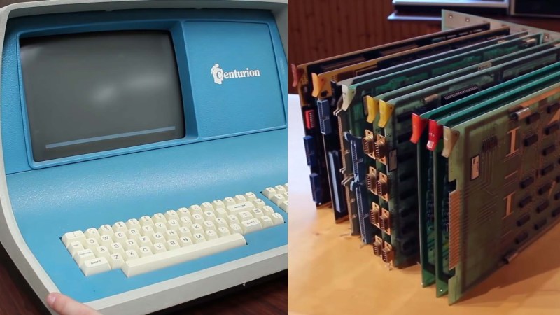
[David Lovett] aka Usagi Electric has spent the last several months dissecting a Centurion minicomputer from 1980. His latest update reveals that the restoration has hit several snags, and bootstrapping this old blue beast is going to be a challenge.
When we last checked in on this project, [David] had built a homebrew ROM reader to backup critical data stored several of the minicomputer’s ROM chips. Since then, the good news is that the Centurion is showing signs of life. Probing the Data Set Ready pin on the default RS232 serial port reveals a stream of data, likely stemming from the ‘CPU6’ board.
Unfortunately, that’s where the good news ends. Adding a terminal to the serial port interrupts this stream of data, and no information appears to be sent or received from any of the three terminals tested. To make matters worse, both of the massive hard drives appeared to have suffered catastrophic head crashes at some point in the 1990s, destroying the Centurion operating system and likely other important data in the process. Soiled air filters were the likely culprits, with evidence showing that yearly maintenance had been overlooked. While at least one of the drives can be repaired with new platters, the original operating system is completely lost.
As luck would have it, a previous employee of Centurion was able to provide a wealth of undocumented information that greatly aided in making sense of the minicomputer’s individual components. Incredibly, they were also able to provide a PROM Diagnostic board for the Centurion system. Not only could this board run a barrage of tests, it could also bootstrap the system with TOS (Test Operating System), a bare-bones memory monitor stored on the card’s PROMs. While the diagnostic card itself needs repairs, there’s now the slightest chance that [David] can use TOS as the starting off point for writing new software for the Centurion.
We really can’t wait to see what happens next with this project. We’ve covered some very special vintage computer restorations in the past, such as the cursed Diablo drive from a rare Xerox Alto, not to mention the delicate power-up procedure for an original Apple 1.


Those terminals were current loop with Xon/Xoff so I don’t think you can do a loopback with a simple piece of wire.
He should make some current loop to RS-232 converters. It was in the early days of CCITT I’m not even sure if I can call it RS-232 it was 7 bit not 8 bit and one and a half stop bits from memory. At least with converters (PSU and some opto-couples) he could use a laptop to communicate to the terminals and then reverse the converter to communicate from the laptop to the computer. Then again the laptop may not be able to do one and a half stop bits, perhaps there is software somewhere that will.
The signal he is seeing is just noise and that’s why it goes away when there is a load connected.
The current isn’t supplied from the send of each side. The DCE (computer) provided the current and the DTE was the passive end. (from memory).
Here is something like it – the actual current is probably different but it’s the same principle –
https://ub.fnwi.uva.nl/computermuseum/currentloop.html
The Terminal is a ADDS Regent 100, and the connector has EIA Current Loop written under it, but it’s actually capable of doing both current loop or RS-232. If you look closely at 9:42 you can actually see the DIP switch for selecting between current loop or RS-232.
And actually, the terminal is totally working fine now! It turns out it was just user error.
There were two problems I was butting my head against.
The first is that the DIP switch ON/OFF positions are opposite what the writing on the back shows. The writing shows 1 as up and 0 as down, and the dip switches are 0 up and 1 down. I actually figured this out in-between filming the main shots and the close up shots of me flipping the DIP switches. I found the manual for the Regent 200 last night and it actually mentions this, but there’s no indication on the back of the machine for it.
The other problem was that this terminal really, really doesn’t like you flipping DIP switches with it powered up. The terminal needs to be switched off, the DIP switches flipped, and then powered on again. Not sure if that’s normal or not, but I flipped the power off, put it in Full-Duplex (now that I knew the proper state of the DIP switches), turned Self-Echo off, jumped pins 2 and 3 and powered it up again and it’s looping back perfectly.
Typing gives one character back, and even hitting New Line and Line Feed actually moves the cursor like normal instead of printing “CR” or “LF” on the screen.
“The other problem was that this terminal really, really doesn’t like you flipping DIP switches with it powered up. The terminal needs to be switched off, the DIP switches flipped, and then powered on again. ”
This is the way that virtually all older equipment, and at least some new equipment, works. The older equipment at least had the excuse of not being fast enough/having enough code space in an expensive UVEPROM to constantly loop and check the state of the switches and look for changes during normal operation. I don’t think I’ve ever seen an example of DIP switches being interrupt driven.
Those disks may have some ugly crashes in them, but but there still may be readable data on the good portion of the platter. Would be difficult but not impossible
That was what I was thinking. The data density on those disks is very low even lower on the outer tracks.
Put the disk on a 3D printer bed and attach a magnetic sensor to the print head. Perhaps a helical scan so there’s only one sync per revolution to minimise the GCODE integration.
I think you guys just might be onto something here.
That data density really is ridiculously low by modern standards. I read (IIRC here?) about some bloke who had a much more modern drive than had a dead spindle motor, so he attached an electric drill to the hub and managed to get data off it.
Would it be possible to temporarily re-purpose the Hawk drive itself for a while?
Firstly, get the drive operational to the point where the voice coil circuitry can step the heads to all tracks. Bit-bash an Arduino to inject step pulses. Then remove the heads and make a bespoke extension for a Hall Effect sensor (Arduino controlled).
Then disconnect the platter drive motor and attach an (Arduino-controlled) stepper directly to the hub pulley underneath, to spin the disk very slowly. Perhaps it could tap off the drive’s index hole(s) sensor.
Now I’m assuming there is some way to calibrate the VC but I don’t know. If there is you could set the head alignment to the outer limit and attempt a read of all tracks. Nudge the alignment a bit, and try a complete read again.
And so on and so on.
I would find it very hard to use any of the original equipment apart from the platter.
To use a modern and far superior magnetic sensor you would have to design a head magnetic former and the aerodynamics of the head to “fly” and it’s not going “fly” well over the area of that gaping head crash resulting in … well another head crash.
Instead I would put it on a (very well levelled) bed of a (large enough) 3D printer and get the magnetic sensor and former (suspended on the print head) as close a practical. If things were still difficult you could use TOF distance measurement to see if you can get closer in the recess of the head crash area and hope! There’s probably not a lot of ferric material left there and depending on what the base substrate is (inner disk) there may well be no magnetism left.
After that you could try thin Kapton coating on the disk and indirect contact.
As a last resort you could try contact sensing with lubrication and Teflon on the sensor in near clean room conditions. That “one” speck of dust!
All of this will take time and probably quite a lot of time but the technology is sitting there waiting and this is probably the last chance to get this OS. There is no harm in trying and great benefit in giving it a decent attempt and succeeding.
This old equipment never got anywhere near Nycrist theorem due to other limitations so there could hundreds of cycles to a single bit.
I don’t know the capacity of the platter but graph it to bits in a circle at full scale and you’ll see what I mean.
You’ve raised fair enough points. Certainly agree with the lubricant, something like the silicone/teflon stuff used for treadmills comes to mind.
As for spinning, the point would be to rotate it as slowly and carefully as possible NOT try to get data off as fast as possible which of course was the original objective. But, maybe a force-measured Z-axis lift that a 3D printer has could really help too.
Noob question: is there a relationship between rotation speed and capability of “reading” the magnetic state of a disk/tape location? Asked differently: is it possible to scan and map the complete surface magnetization’s states by probing statically (no rotation) or at extremely low speed? And what kind of sensors could be used beside original drive’s head?
There is normally serval relationships with speed.
The first and obvious is frequency of the read signal. Faster rotation will increase the read-back frequency.
The second is related to the fact that a normal head sensor is an inductor and the higher the rate of change of the magnetism (faster disk speed) the higher the (AC) voltage across the inductor. This however does not necessarily translate to higher power so it doesn’t necessarily improve the sensitivity of the read inductor. In reality it is likely to go the other way because of the increase of frequency.
Modern magnetic sensors that may be used here used here use the (magnetic) field effect transistor. They can be extremely sensitive and some even give data on three axes (x,y,z). There often used as current sensors now as well. They will read static values so yes a slow scan can be done on a 3D printer or CNC device. They can even be bought in a quad sensor (in a single chip) arranged as a Wheatstone bridge to give highly linear proportional readings of the static field strength just add your favourite instrumentation amp and logger.
After seeing the platter removed from the spindle I really don’t think trying to read it in rotation is a good idea.
These things were very hard to (track) align when new, add several decades of bearing wear and head carriage backlash and it would be near impossible.
Thinking about this, the magnetic bits were originally written as little arcs using a polar coordinate arrangement. Woudn’t reading the magnetic pattern as a grid of x,y coordinates yield possibly false results?
Interesting! Scanning a whole surface would allow to avoid all the tracking problems (either with circular tracks on a disk or helical scan tracks on a tape).
But i wonder what kind of “resolution” one could achieve with some modern sensor? Compared to various data densities, would it be enough to resolve individual bits?
And also, would it work for analog recordings?
David,
I think the problems you’re having are because you not using any vacuum tubes in the restoration.
B^)