A vintage film camera with a bright light emitting diode shining through it, next to electronic equipment to measure the shutter speed

Clock Your Camera With This Shutter Speed Tester

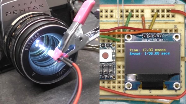
Camera shutter speed is an essential adjustment in photography – along with the aperture, the shutter moderates the amount of light entering the camera. Older cameras (and some newer ones) use mechanical shutters that creep out-of-spec over the years, so [Dean Segovis] built a handy shutter speed tester.

With just a handful of basic components, this project is a great one for beginners to sink their teeth into. The tester is based around a photoresistor that measures light from another source (a flashlight) that travels through the camera body. When the shutter on the camera is released, the shutter speed can be measured and displayed on the OLED screen. An Arduino naturally handles all the computational duties. The whole thing can be easily assembled on a breadboard in just a couple of minutes.

The original project by [hiroshootsfilm] is over on Project Hub, however [Dean] takes a deeper dive with some code troubleshooting, as well as trying out a variety of old film cameras with the breadboard tester. His testing revealed that the photoresistor was better able to detect shutter speed when the camera lens was removed, which is a hot tip for anyone else that wants to try this.

While it’s not surprising that these older cameras are having trouble with their mechanical shutters, this little tester would be an invaluable tool when it comes time to start tweaking shutter mechanisms. If this project has brought out the shutterbug in you, make sure to check out this brain transplant for a Polaroid 100-series Packfilm camera that we covered way back in 2011.

Continue reading “Clock Your Camera With This Shutter Speed Tester”

A visually accurate replica of the MCM/70 computer, an all in one system with a keyboard, dual cassette drives and a small one line display

MCM/70 Replica Embodies Proud Canadian Heritage

When a vintage computer is all but unobtanium, software emulation is often all that remains. Unless you are [Michael Gardi], who saw an opportunity to reproduce Canada’s home-grown MCM/70 microcomputer using a combination of software emulation and modern hardware.

Short of building a brand new MCM/70 from the original schematics, this faithful facsimile of the MCM/70 does everything it can to pay homage to the original machine. The foundations of this project can be attributed to the York University Computer Museum (YUCoM) MCM/70E emulator, highly regarded for its “historical accuracy”. The MCM/70 used dual cassette tapes for storage and a funky 32-character dot matrix plasma display, which is all reproduced in software (other versions dropped one of the cassette drives for a modem, bleeding edge innovation for 1974 microcomputing).

From here, [Michael] set off to assemble the various physical components of the original computer. The chassis itself was built from scratch using a mixture of 3D printing and traditional woodwork. The high-voltage plasma display was recreated using four HCMS-2972 dot matrix modules, which minor compromises. The original computer used display memory as extra storage when executing instructions, which created a sporadic blinkenlights effect on the original display. This new display unfortunately won’t reproduce this ‘thinking’ pattern, but it’s a small sacrifice.

Similarly, the original keyboard was going to be challenging to replicate with 100% accuracy, so a brand-new recreation of an Ohio Scientific computer keyboard was used instead. The layouts are extremely similar, and anyone except your most committed Canadian retro computing enthusiasts probably wouldn’t notice the difference. Being a modern recreation of a vintage keyboard, this was relatively easy to source. A set of custom-made keycaps with APL legends really helped sell the replica.

And while working dual cassette drives would have brought this project home, it’s commendable that [Michael] has created ‘working’ cassette drives using 3D printed cassettes and some magnetic magic using hall effect sensors to identify the loaded cassette. The emulator incorporates three virtual cassette tapes which made this solution possible.

If this all sounds familiar, it might be because this project was based on a superb Hackaday writeup of the MCM/70. A truly innovative computer for its time, the story behind Micro Computer Machines (not to be confused with the toy cars) is a fascinating tale, and the write-up is worth a read if you haven’t seen it already.

Continue reading “MCM/70 Replica Embodies Proud Canadian Heritage”

A small electronic board next to colorful stylized speaker

Soundscape Sculpture Is Pleasing Art For Your Ears

Artist and self-described “maker of objects” [Daric Gill] is sharing some of the world’s most pleasing and acoustically interesting soundscapes with museum patrons in his latest work, ‘The Memory Machine: Sound‘.

Now featured at the Center of Science and Industry museum, the interactive stereo soundscape generator resembles three decorated ‘tree trunks’, suspended high above the exhibition floor. When visitors approach the artwork, they are treated to a randomly selected soundscape sample.

The build, which is described in blog form here, teases just some of the sixty soundscape samples that can be heard. These include the noisy chattering of crowds underneath the Eiffel Tower in Paris, the mellow melodies of a meadow high in the Swiss Alps, and the pumping atmosphere of a baseball match played in Yankee Stadium, New York City.

Only the middle trunk reveals the electronic soul of the installation – an Adafruit M4 Feather Express, Music Maker Featherwing and a motion sensor. The flanking trunks house the speakers and amplifier. The motion sensor triggers the microcontroller, which then plays a randomly selected sample from an SD card.

[Daric] went to great lengths to reuse discarded materials, and even cannibalized parts from other sculptures to see his vision through. This focus underpins a substantial amount of woodworking and machining that went into this build, so the full video is certainly worth a watch to see the whole project come together.

Make sure to check out our coverage of other funky installations, like this mesmerizing ceiling decoration.

Continue reading “Soundscape Sculpture Is Pleasing Art For Your Ears”

A robotic machine turning the wheel of a safe

Adventures In Robotic Safe Cracking

When [Zach Hipps] was faced with a locked safe and no combination, it seemed like calling a locksmith was the only non-destructive option. Well, that or doing something crazy like building a safe-opening robot. Since you’re reading this on Hackaday, we bet you can guess which path he took.

So far, [Zach] has managed to assemble the custom chuck and spindle for the safe cracker. This construction is then mated with an appropriately precise Trinamic controller for the motor, which is perfect for this heist project. After some early consternation around the motor’s stall detection capabilities, the project was able to move forward with extra microcontroller code to ensure that the motor disengages when sensing a ‘hard stop’ during cracking.

Precision is absolutely essential in a project like this. When dealing with a million potential combinations, any potential misconfiguration of the robot could cause it to lose its place and become out-of-sync with the software. This was encountered during testing — while the half-assembled robot was (spoilers) able to open a safe with a known combination, it was only able to do so at slow speed. For a safe with an unknown combination, this slow pace would be impractical.

While the robot isn’t quite ready yet, the Part 1 video below is a great introduction to this particular caper. While we wait for the final results, make sure to check out our previous coverage of another auto dialing robot cracking the code in less than a minute.

Continue reading “Adventures In Robotic Safe Cracking”

A small 16x2 LCD display housed in a green and yellow hobby box.

Arduino-Powered Info Display For Your Windows Computer

If you’ve been pining for a retro-chic 16×2 LCD display to enhance your Windows computing experience, then [mircemk] has got you covered with their neat Windows-based LCD Info Panel.

Your everyday garden variety Arduino is the hero here, sitting between the computer’s USB port and the display to make the magic happen. Using the ‘LCD Smartie‘ software, the display can serve up some of your typical PC stats such as CPU and network utilization, storage capacity etc. It can also display information from BBC World News, email clients, various computer games and a world of other sources using plugins.

It’s clear that the intention here was to include the display inside your typical PC drive bay, but as you can see in the video below, this display can just about fit anywhere. It’s not uncommon to see similar displays on expensive ‘gamer’ peripherals, so this might be an inexpensive way for someone to bring that same LED-lit charm to their next PC build. You probably have these parts sitting in your desk drawer right now.

If you want to get started building your own, there’s more info over on the Hackaday.io page. And if PC notifications aren’t your jam, it’s worth remembering that these 16×2 displays are good for just about anything, like playing Space Invaders.

Continue reading “Arduino-Powered Info Display For Your Windows Computer”

A personal computer drive bay with a glowing LED display

Turbo Button Pays Charming Homage To Early Personal Computers

The PC turbo button and LED clock speed display were common features on early personal computers. Wanting to add a little retro chic to his modern battle-station, [Matthew Frost] assembled a charming and functional homage to the turbo button control panel.

In days past, this automotive nomenclature implied a performance boost when activated. Instead, ‘turbo mode’ would clock your x86 processor at its rated speed. Disabling ‘turbo’ would throttle the CPU, often all the way down to 4.77MHz. Inherited from the original IBM PC, some early computer programs relied on this specific clock speed, and would otherwise run too fast (or not at all) on faster hardware. PC marketing teams and engineers alike stopped including the turbo button and glowing clock speed numbers around the Pentium era.

This modern re-imagining of the turbo button uses an Arduino microcontroller, seven-segment display and tactile switches to emulate the look and feel of the original hardware. Instead of directly adjusting the CPU clock speed, hitting turbo switches between balanced and high-performance Windows power plans. The seven-segment display measures this clock speed in GHz to two decimal places. We’ll admit that it’s pretty satisfying to see those numbers inch higher when switching to turbo.

The rightmost button switches between measuring CPU speed, GPU utilization, network load and memory utilization, which improves on its original inspiration. The tubular key lock, also a common sight on early PCs, enables and disables networking for the entire system, which is great for keeping the kids off the ‘net (at least until they figure out how to remove the 5.25″ drive bay from the system and hot-wire the network adapter with a paperclip).

There are more details on the GitHub page, in case you want to build your own. This project could look especially fetching in PC sleeper builds, where new components are ‘hidden’ in old case hardware. And if this has made you feel nostalgic at all, you may want to hear our thoughts on why it’s all about the Pentiums.

Continue reading “Turbo Button Pays Charming Homage To Early Personal Computers”

A small green circuit board with a tiny OLED display

An Oscilloscope Trigger For Vintage Video Processors

Working on retro computers is rarely straightforward, as [ukmaker] recently found out while designing a new display interface. Their oscilloscope was having trouble triggering on the video signal produced by older video circuitry, so they created the Video Trigger for Retrocomputers.

The Texas Instruments TMS9918 video display controller was used across a range of 1980s game consoles and home computers, from the well-known ColecoVision to Texas Instruments’ own TI-99/4. Substantial retro computing heritage notwithstanding, the video output from this chip was (for reasons unknown) not quite compatible with the Hantek DSO1502P oscilloscope. And without a better understanding of the video signal, it was difficult to use the chip with newer TFT displays, being designed for CRT televisions with more forgiving NTSC tolerances.

Maybe a different scope would have solved the problem, but [ukmaker] had a feeling that the ‘scope needed an external trigger signal. The Video Trigger project uses a LM1881 sync separator to tease out the horizontal and vertical sync signals from the vintage video chip, with the output piped into an ATmega 328P. Along with a smattering of discrete components, the ATmega aids the user in selecting which line to frame a trigger on, and the slope of the horizontal sync signal to align to. A tiny OLED display makes configuration easy.

If this has piqued your interest, [ukmaker] also has a great write-up over on GitHub with all the gory details. Maybe it will help you in your next vintage computing caper. Having the right tool can make all the difference, like this homebrew logic meter for hobby electronics troubleshooting. Or if you want to know more about the mystical properties of analog NTSC video, we’ve covered that, too.