Grounding of electrical systems is an often forgotten yet important design consideration. Issues with proper grounding can be complicated, confusing, and downright frustrating to solve. So much so that engineers can spend their entire careers specializing in grounding and bonding. [Bsilvereagle] was running into just this sort of frustrating problem while attempting to send audio from a Nintendo Switch into a PC, and documented some of the ways he attempted to fix a common problem known as a ground loop.
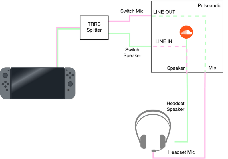
Ground loops occur when there are multiple paths to ground, especially in wires carrying signals. The low impedance path creates oscillations and ringing which is especially problematic for audio. When sending the Switch audio into a computer a loop like this formed. [Bsilvereagle] set about solving the issue using an isolating transformer. It took a few revisions, but eventually they settled on a circuit which improved sound quality tremendously. With that out of the way, the task of mixing the Switch audio with sources from other devices could finally proceed unimpeded.
As an investigation into a nuisance problem, this project goes into quite a bit of depth about ground loops and carrying signals over various transforming devices. It’s a great read if you’ve ever been stumped by a mysterious noise in a project. If you’ve never heard of a ground loop before, take a look at this guide to we featured a few years ago.


Nice. Mine would always leak noise into the audio whenever the game loads something.
It’s too bad the system is so picky with USB DACs, none of mine work.
If you have a DAC that has optical input, you can purchase an HDMI audio extractor that can send the audio path from the HDMI cable to an optical cable into the DAC. That way, any DAC with an optical input will work.
That 180 degree flip at 3 kHz is _way_ too sharp to be real. Maybe the Diligent and its PC software dropped some samples.
180 degree phase offset is exactly the same as -180 degree phase offset. It is perfectly normal for graphs to wrap around at that point, though smart software adjusts the range to make the graph continuous.
PEBKAC issue.
Years ago when I was right into car audio it was quite common to put isolation transformers in your system. Most car audio shops like this
https://cdn11.bigcommerce.com/s-d97c0/images/stencil/1280×1280/products/5318/21562/01__98883.1584945596.jpg?c=2
Optocouplers help a lot, for the signal path.
“Ground loops occur when there are multiple paths to ground, especially in wires carrying signals. ”
Ground loops occur when there are multiple paths from the SAME POINT to ground, That creates a complete path (“loop”) that can conduct current, and that current induces noise into the audio path.
“The low impedance path creates oscillations and ringing which is especially problematic for audio. ”
Not quite right. As above, noise comes from the current (induced by eg AC fields or potential differences) that flows in a ground loop. I’ve never encountered oscillation or ringing in an audio-related ground loop. RF circuits are a different matter.
Transformers are usually very effective at isolation and breaking ground loops, but audio transformers good enough for professional or hi-fi applications can cost $20 and up each. So they are the fix of last resort.
I have no idea how this comment ended up in response to the comment about optoisolators. But since we’re here… optocouplers can’t be used in analog signal paths.
Actually optoisolators can do very well indeed in analog signals. Not at all like the above comment implies, of course, but a pair (or four) in the feedback loop of an opamp works very well up to many kHz. Driven within reason they are intrinsically linear, and the feedback loop takes out the remaining woogles.
And of course there’s TOSLINK, which is sort of a digital cheat but *is* optical isolation, and can stand off a few megavolts and still provide two channels with 20 kHz bandwidth.
Digital ain’t analog so TOSlink doesn’t qualify.
What optocoupler would you recommend that’s sufficiently linear and wide-band for hifi audio? I assume you aren’t referring to LDRs (light-dependent resistors).
This might help:
https://www.ixysic.com/home/pdfs.nsf/www/AN-107.pdf/$file/AN-107.pdf
You can do similar things with plain old optocouplers, provided they are analog (not logic) and not darlington output (they’re too slow).
I have a couple of Radio Shack RCA ones. One did great and still works well today. As a renter I was often faced with poorly or improperly wired residences that further complicated issues. Add my own built idiotic noise makers and such and it taught me a lot about that annoying hum. Then if you add midi and some builders and companies tossing the optocoupling and that added another layer to contend with. I had always thought that part of the midi standard had been fairly brilliant. When folks treat it as a dumb serial port on audio equipment going to gpios etc there can be a relapse of history.
Thanks Paul, but that’s a telephone-grade device… hardly hifi. At its best:
‘Use photovoltaic mode where up to 40KHz
bandwidth is required and linearity comparable to a
13-to-14 bit D/A converter with ±1 LSB linearity error
(0.01%) is acceptable.”
Along with the IXYS LOC series, there’s also the classic HCNR200, now a Broadcom product. It will do about 1 MHz and was used in isolated scope applications such as the Tektronix THS700 series. That’s about as analog as it gets.
I don’t know how this ended up here, sorry. Anyway, Optocouplers aren’t good at distortion-free transmission of analog signals.
HCNR200
Thanks. This might be good enough for gamers or telephony, but doesn’t reach CD quality.
Is the ground loop due to the switch being grounded through its dock, or just the two audio cables from the TRRS splitter?
Ideal ground in electronic must be in 1 point. You even saw it in old tube type audio. Also in some cars.
1st time I read it in my dad’s book from 1965. Then I learned more about the groud point when I got my fisrt oscilloscope.
I cannot insert a pictire, but here is the link: https://res.cloudinary.com/rs-designspark-live/image/upload/c_limit,w_1024/f_auto/v1/article/picture_5A1_c52f97b3324492988747ae09229345d666a52d29
Single-point (aka “star-ground”) is in most cases the approach. And in demanding situations, it’s not trivial to deal with a mix of devices.
https://www.ranecommercial.com/legacy/note151.html
It’s an often misunderstood subject. I’ve found Robert Feranecs videos on the subject to be very enlightening. Even though it’s about PCBs, the general concepts also apply to wiring:
https://www.youtube.com/results?search_query=feranec+ground
Re-reading the posted article, the best fix would be to re-wire the headphones so that the mic signal path and the headphone path are completely separate, with no shared ground. Then the only ground-loop isolation required (if necessary) would be between the Switch line out and the headphone amp’s line in.
Ground loops gave me problems in my steel slide self-sustaining guitar between the Digitech processor and the amp caused by the switching reg in the Digitech, whine in the background. After trying many ways of hooking it up I decided that transformers would be the way. No whine now. This instrument is battery powered and self contained. A total of 3 transformers are in it. One at the input to the processor and 2 more on the output when I feed a board.
Today I have to travel to the next state over and put some of those car stereo transformers into a organ and amps in a church. We normally go direct and have no noise issues but this time hum went rampant. I hope this is the fix.
My approach to system noise issues is to start with the minimum connected, then add sources one at a time. For example, have nothing but amplifier connected to speakers… and that should be near dead quiet, no hum, buzz or hiss, regardless of control settings. Any issue at ths point is the amp, or how the amp is grounded. Then connect the mixer (if there is one), then connect sources one at a time to the mixer. It usually turns out that connecting one specific source causes issues, so then it’s down to determining why connecting that device causes problems. And maybe you will find a connection or cable problem… and worst case you have your transformers if there’s no other simple fix.
Good luck.
3.5 mm ground loop isolator : https://www.google.com/search?q=3.5mm+ground+loop+isolator+adapter+aukey&client=ms-android-google&sa=X&biw=412&bih=677&tbm=shop&sxsrf=APq-WBs5VExD7grWuwCWtDEYFCIz0B32jA%3A1648480849172&ei=UdJBYtvhCYuS0PEP0ua92As&oq=3.5mm+ground+loop+isolator+adapter+aukey&gs_lcp=Cg5tb2JpbGUtc2gtc2VycBADOgcIIxCwAxAnOgUIIRCgAToHCCEQChCgAUoECEEYAVC9BVibEGCkEWgAcAB4AIABjQGIAd4FkgEDMi41mAEAoAEBqgESbW9iaWxlLXNoLXdpei1zZXJwyAEBwAEB&sclient=mobile-sh-serp
It’s getting close to time to start thinking about retiring consumer analog headphones. We should be looking at putting a second USB-C port where the jack is, car stereos should act like usb soubdcards, etc.
If someone does want analog, they’re probably an audiophile and want to choose their own amp and DAC anyway.
Very slim included inline dongles can bridge the
gap with legacy stuff. I think the tech is ready to move on without too much trouble.
It’s definitely nowhere near that time yet, I know phones have gotten rid of audio jack’s but look how many people complained about that. Too many devices are still in use that use normal analogue headphones, most PCs still do, a lot of laptops do, etc, and it makes it very easy to connect in other devices like speakers or to split the signal. I can’t see it being very easy to split a USBC audio signal, since USB is supposed to be between two devices and not split. You could use a USB hub but then the devices probably will show up as separate audio outputs on your device so you’ll need some extra software to output to all of them at the same time. I also think USBC is probably weaker than a 3.5mm plug, and since cables tend to be pulled and yanked etc, then it maybe better staying with 3.5mm. Theres also nothing wrong with 3.5mm analogue, and I can’t see any advantages to using USBC, especially since you usually want a separate audio output anyway. So why would you change it if it has more disadvantages than advantages?
I sure would like to know a source for those Kript HiFi transformers inside the enclosure. They would work well in a device I designed awhile back. I had pins pulling out of the brand I use under vibration before adding mitigation.
Another technique is a ground-cancelling output. The ground contact on the output connector is floated. The voltage on the ground contact is sensed and added to the signal fed to the hot contact.
Usually this is less expensive than a transformer, has better phase and frequency response, and less distortion. Noise rejection without trimming may not be as good, and there are limits to the rejected voltage and radio frequency rejection.
Lookup USB Audio and find one that works with win98se (eBay). Those will work fine on the switch. It’s how I fixed the annoying ground loop issue on my end.