
RS485 is a communication standard that should be part of the advanced hardware hacker’s arsenal; it’s not commonly encountered, but powerful exactly when you need it. It’s a physical layer interface for wired communications that uses a single differential pair for noise immunity, has good long-distance properties, and allows many connections to a single bus. Because of that, you will encounter it in security systems and even cameras, wired sensor networks, DMX512 lighting and all sorts of industrial electronics. For our hobbyist goals, you can absolutely use RS485 to build your home (or room) automation system, or a relatively large robot – without all those worries that wireless brings.
The name might remind you of RS232, and that’s because both RS232 and RS485 are standards that come from EIA (Electronics Industries Alliance). It also might remind you of RS422, if you’ve ever seen this name mentioned online – RS422 and RS485 are closely intertwined, sharing most of the physical layer, and I’ll show how exactly they relate.
Physical Layer
At its simplest, a RS485 link is akin to a UART communications channel, but differential and half-duplex, with TX and RX combined into a single communications line. Bytes sent as unclocked data at a pre-arranged baud rate, so your USB-UART adapter or MCU’s UART peripheral will work for most RS485 purposes. Just like with UART, there are only a few commonly used baud rates, so it should be easy to guess. The differential signal means that you will need to use special transmitters and receivers for working with RS485 links – they aren’t pricey, so it’s wise to have a few in stock before the day when you could really use it.
One of the main benefits of RS485 is that you can put multiple devices on a single link. This is a pleasant difference from logic-level UART or RS232, especially for our sensor and other smart device network building needs. The tradeoff is that an RS485 link is half-duplex – that is, two or more devices cannot transmit at the same moment of time.
If you ever really need a full-duplex connection, where devices X and Y might want to transmit without regard for each other, you will want to use two RS485 links – one link for a “X transmits, Y receives” direction and other for the “Y transmits, X receives” direction, point-to-point style. Congratulations, you’ve invented RS422, but you’ve lost the very useful bus nature of RS485.
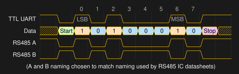
Signals are transmitted differentially. In place of one signal, there are two signals: one is always opposite the other – when you transmit a high logic level, line A goes high and line B goes low, and when you transmit a low logic level, line A goes low and line B goes high. The receiver doesn’t measure the absolute level of the signals relative to ground – instead, it measures the difference between them. We have talked about differential pairs before, explaining their benefits like high noise reduction. Using differential pairs is what allows for RS485 links hundreds of meters long that you will see people online brag about building!
One fun part about RS485 is the A/B naming conventions. In the last paragraph, I’ve used “A” and “B” as “non-inverting” and “inverting” signals respectively – that is, voltage on “A” has the same polarity as the logic level of the signal transmitted, but voltage on “B” is the opposite of it.
The RS485 standard, as it’s written, actually has the opposite meaning for these two – “A” is inverting and “B” is non-inverting. However, the RS485 transciever makers have all (consistently) reversed them relative to the standard, to the point where Wikipedia has a good few paragraphs complaining about it. When it comes to the naming convention being used in this article, I will use the signal names you will actually deal with when it comes to RS485 ICs and devices, as opposed to the ones defined in the standard but not actually respected by devices you will encounter. It might be better if the world standardized on “D+” and “D-” as with USB, but that ship has sailed.
Differential Implications
The difference between two signals, rather than their voltage relative to a common ground, is what the controller actually cares about. What happens if they’re close to each other – say, there’s no transmitter driving the line at the moment? If the difference between A and B is within 200 mV, the signal is considered invalid, and your receivers might get confused, or, at best, reject it. To avoid this, biasing resistors are typically used – a pullup on A and a pulldown on B. The typical biasing resistor values are calculated to create a voltage a bit over 200 mV (to account for noise) on receiver inputs after accounting with the cable impedance and termination resistors – essentially, calculating a three-resistor voltage divider.
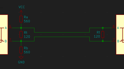
Common practice is to put two resistors in one spot, and have them do all the biasing work. You can absolutely ballpark something like 500 ohms worth of pull, and this appnote has a straightforward formula on page 4 if you’d like to know more – a simple resistor divider calculation is all it takes. There’s more to the bus, however – let’s dive into the layout and termination requirements.
In differential links like this, especially as speeds get higher, impedance starts to matter – which, in large part, is a requirement for the cabling you use. For a start, it has to be a twisted pair. The recommended impedance for RS485 links is 120 ohms and that’s what RS485 hardware is typically designed for, but for many hobbyist applications, you can absolutely use one of the pairs in an Ethernet cable (100 ohms) or a decent USB cable (90 ohms) and call it a day.
For impedance matching and reflection dampening reasons, RS485 also requires that you add termination resistors at the ends of the network – they’re typically 120 ohms. Typical RS485 modules you can get come with 120R termination resistors, and you likely won’t need to adjust them to match your cable’s impedance – but you will need to remove the termination resistors that are not on the ends of the daisy chain! Interested in more explanations of why termination matters, with pretty graphs and explanations of all the different types of termination possible? This appnote will help you, too.
The RS485 bus doesn’t lend itself to stubs, and especially not to star topology networks – pulling the same link into multiple different directions is heavily discouraged due to reflections caused by signal coming back from ends of multiple different branches at once, and difficulties properly terminating such a topology. The best network will result from daisy-chaining the devices, as in, having them in a straight line, with RS485 devices connected inline, stubs as short as reasonably possible — under six inches is the usual guideline, but less is better.
Ok, Ok, How Do I Start?
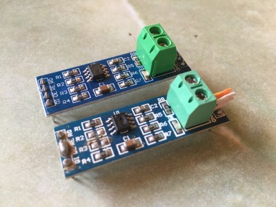
So how do you actually get into RS485, as a hobbyist just learning about the powers it gives you? If you look up “RS485” at your online retailer of choice, you will encounter these cheap elongated blue modules with pin headers and a terminal block – and feel free to just get those. Most of them have clones of the MAX485 IC – one of the many IC designs for talking RS485 and certainly a staple of RS485 hardware, others being generally pin-compatible for the same feature set, like SN75176 and SP485.
These PCBs come with 120 Ω termination resistors and 20 kΩ biasing resistors – you will likely want to change these. Remove the termination resistors for any modules not at the ends of the link, and replace biasing resistors with those that get you to a stable bus idle voltage point – a pair of 560 Ω resistors on one of the modules will do well for biasing.
The MAX485 works with a single RS485 link, so it is half-duplex: you have to switch it between receiving and transmitting. On the MAX485, transmitter and receiver enable inputs are two different pins, but basically everybody joins them into one pin. This is possible because the RE (Receiver Enable) signal is inverted, and this lets you switch between transmit and receive with a single GPIO. Essentially, you short pins 2 and 3 of the MAX485 together, either with a jumper wire or with a tactically placed drop of solder, then set them to a low logic level for receiving or high logic level for transmitting with a GPIO. If you’re using a USB-UART or UART peripheral, check if you have the RTS signal available to you – it can be directly wired to a RS485 transceiver’s ~RE and DE for seamless RS485 link operation!
You can buy these “MAX485” modules and mostly be set, but the ICs on them are clones and might burn out on you every now and then. Getting some legit MAX485 ICs from a reputable store and replacing them with your hot air station of choice is a good idea if you want your setup to be reliable. One of the problems with MAX485 is that it requires 5 V and might not work at 3.3 V, so you might as well get some MAX3485 chips and solve both of these problems in one go. Otherwise, if you got a Raspberry Pi in one hand and a cheap “MAX485” module in the other, feel free to use any of the level shifting options, from using one of the usual logic level shifters to simply pulling the VCC of MAX485 down with a diode.
With all this customization and rework, you’re probably thinking you might as well design your own RS485 interface. If you’ve already committed to a PCB design for the project, you’re probably right.
Adding More Devices
The RS485 physical layer lets you put many devices on the same link, like I2C. You cannot do that with three devices that have UART. The requirement, again, is that you only ever have one transmitter active at a time – so, by default, you’d have all transmitters on all devices disabled, and only enabled at a time when one device needs to say something.
The maximum number of devices that you can put on a single bus is described through the concept of “unit load”, a function of the input impedance of receivers and the biasing. In other words, receivers put a certain amount of load on the transmission line, and when the line is loaded too much, the signal levels get too low. The unit load values of your ICs can be found in their respective datasheets, with typical values resulting in up to 32 receivers on a single bus, and available transceiver ICs with low enough unit load that lets you get that number up to 256.
For your own RS485 communications on a multi-drop network, you’d want some kind of transmission protocol that has coexistence and addressing in mind. There’s one popular and powerful option you’ll want to know about, and that is Modbus RTU! It is a data protocol you can use on top of RS485, suited for links with a single controller and multiple peripherals. It’s a commercially successful yet open protocol – which is to say, you can speak Modbus in between your own devices, but also to a large range of devices like heavy-duty machinery or energy meters. There’s plenty of decent libraries for Modbus communications for environments like Python and Arduino to do most of the job for you.
You might notice that the “single controller, multiple peripherals” principle is similar to I2C, and that’s not the only way where Modbus and I2C are alike. For a start, Modbus peripherals, too, have addresses. The way that data is accessed in Modbus is also similar to the register-based system that the more advanced I2C devices have: each Modbus device has registers you can read from or write into. Writable registers tend to be referred to as coils, read-only registers tend to be referred to as inputs, and there’s generally agreed-upon register address ranges telling you at a glance which are which. When building makeshift Modbus devices, however, you are free to break these conventions if it suits you.
Keeping Things Grounded
![Quote saying "[...] lack of ground can result in high common-mode offset voltage on one of the ends. "](https://hackaday.com/wp-content/uploads/2022/03/hadqib_rs485_101_6.png?w=400) “Do you need a ground connection for a RS485 link?” is a hotly debated question, just like “do I need to tie my USB port shield to ground”. You will see a lot of people say that a ground reference isn’t technically needed – after all, it’s a differential signal, and at most, shielding could be called for. This will generally work, even! However, lack of ground can result in high common-mode (relative to ground) offset voltage on one of the ends, and while RS485 transceiver ICs can handle quite a bit of that, it can cause issues depending on the kind of devices in your network.
“Do you need a ground connection for a RS485 link?” is a hotly debated question, just like “do I need to tie my USB port shield to ground”. You will see a lot of people say that a ground reference isn’t technically needed – after all, it’s a differential signal, and at most, shielding could be called for. This will generally work, even! However, lack of ground can result in high common-mode (relative to ground) offset voltage on one of the ends, and while RS485 transceiver ICs can handle quite a bit of that, it can cause issues depending on the kind of devices in your network.
If you’re running a link between devices powered by un-earthed wall-wart PSUs, pulling a common voltage reference along is likely wise. The same goes for a network of battery-powered devices, since voltage induced on one end of the network will happily go onto transceiver inputs of other devices that, in turn, might be capacitively coupled to somewhere else. Not to mention that noise finds a way.
If you are using earthed PSUs on both sides, however, running a separate ground line might create a ground loop. If the “ground” potential at two different locations is wildly different, you may also end up pulling considerable, undesirable current through the common path. Remeber that the two transceivers need a common middle voltage reference, but it need not be “ground”.
If grounding had straightforward answers, we hackers wouldn’t have so many conflicting opinions about it. In case your ground issues get really unmanageable, you can get isolated RS485 transceivers, or, on a budget, use a few 6N137 high-speed optocouplers, maybe even one of those isolated DC-DCs. Typically, there’s solutions available for any RS485 problems you encounter, and people have made RS485 links work in pretty grim circumstances.
When It Goes Wrong – Or Right
If you experience a noticeable amount of data loss or corruption, it’s worth poking your transmission line with a scope or a multimeter. Is the bus idle state within voltage margins, at different points in the network? Do you have ringing on the signal, and how “bad” is it relative to the norm and the signal levels you’d expect? Does ringing change depending on how far the device is in the chain? Echo your Modbus (or other protocol) packets into a debug console – do they arrive intact?
 With this knowledge of RS485, you won’t just be able to gain control of more and more powerful devices out there, you will also figure out some fun things that will help you in other areas. For instance, you don’t have to put UART-like communications through a RS485 transceiver, you can simply use it for transmitting the state of a GPIO in a noisy environment. Or you can use an RS485 transmitter to dramatically extend range and stability of WS2812 LED protocol communications, especially when you have high-voltage lines running close to your LED strips.
There’s an idea floating around that you could use the transmitter section of an RS485 driver IC to drive small vibromotors as an improvised cheap H-bridge – and get yourself some fancy haptics-capable hardware as a result. Small-footprint H-bridges, especially for low-power electronics, can get expensive, chip shortages don’t help either – yet RS485 transceivers are cheap and still abundant. Who wants to bet that this will work?
Terminating These Thoughts
RS485 is an underappreciated topic, and while wireless links are enticing, there’s plenty of space for good old rugged differential communications. Whether you’d like a protocol you can understand, an interference-resilient communications channel, or an inherently secure physical layer for your network, RS485 is here for you. With one more tool in your arsenal, may you design wired long-distance links like never before.


RS485 is commonly used to control the spindle VFD on hobby CNC routers.
That would be the Modbus RTU part.
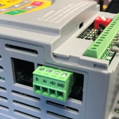
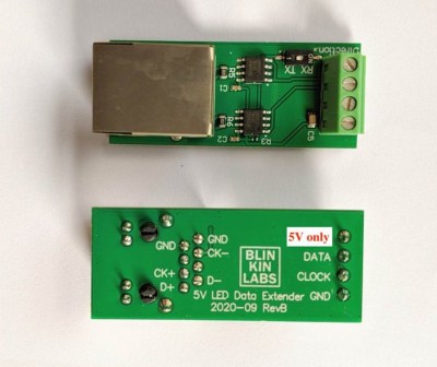
For sure! That was my first thought when I saw that top square image with the B- / A+ labelling.
IIRC DMX is basically RS485
Correct, DMX uses RS-485.
This module makes use of RS-485 as well: https://hackaday.io/project/179020-diff-powerdata-to-leds-and-devices-over-rj45
Yay! This is what got me into arduino years ago – we were buying network controllable power strips at work, but I spotted that a serial version was much cheaper, and pitched that we’d buy the serial version plus a pile of arduino + Ethernet shields to network them ourselves and save several grand. The strips turned out to be RS485, so get got a tube of those driver chips.
Of course, when they arrived, we found you could pre-program them with a delayed switch-on when they were powered up, which was 95% of what we wanted to do with them, and so we never networked them, and I got a big box of arduinos and Ethernet shields to play with. :) everyone won!
I’ve taken to using CAN transceivers instead of RS-485 transceivers; no stress on the parts when two devices transmit at the same time. (An yes, this is one async serial ports.) This eases the restraints on the protocol (to not need to be so concerned about collisions). Though a word of warning; keep your baud rate above a minimum value. Most CAN transceivers have a stuck-transmitter failsafe that will trigger on a null sent at 19200bps. I found 57600bps working just fine, though.
CAN is very slow in comparison to what baud rates you can get with RS485, and CAN is not suitable for the low latency communication. I use a full duplex RS485 at over 10mbps with a time.sensitive protocol – a single node commands the tick start, the other send their responses in their dedicated time slots. Used this architecture in a few industrial applications, always worked perfectly, with a guaranteed latency and a high data rate.
Interesting!: Is your work open-sourced or under NDA/proprietary?
It’s proprietary, so I can only share very limited details. But the general idea is very simple – instead of all that complex TSN-style time sync, have a single master node that gives a tick to everyone else, and the other nodes time their response off this tick every time. So it does not matter if clocks get out of sync, they won’t drift too much within this 1ms interval between the master ticks.
Modbus RTU over RS485 basically behaves like SPI, but over much longer distances, and requires only two wires instead of four (or more). The modbus client (SPI master) either sets or gets data from modbus server (SPI slave) nodes using pre-defined register addresses. The clients then respond (if it’s a get). It makes deterministic timing relatively easy. This assumes that all the nodes have a common pre-defined clock setting negotiated in advance (so no clock line is required).
Please note I’m not suggesting that spi is compatible with modbus, just that they function very similarly.
I hate half duplex with a burning passion. Differential signals are fine, I don’t consider them essential fpr most things but they’re fine. Half duplex signals though jave caused more issues than I can count, especially with vendoes of rs485 devices having many and vaiired specs for how they use that physical layer. I would never be so cheap as to not drag 2 more wires into it and double the number of transceivers for robustness.
In some situations, you simply cannot afford the extra pair (neutrally buoyant underwater tethers where buoyancy & overall OD is a good example), and in others you’re dealing with legacy infrastructure and you get just one pair for all of your comms. The issue with RS-485 is that it only specifies the physical/electrical layers, and no two manufacturers implement the layers above consistently. That’s where things like ModBUS et. al come in.
RS-485 defines “part” of the physical layer of the ISO OSI 7 layer model: (https://www.imperva.com/learn/application-security/osi-model/) and it’s been around since the 80s. So it should be no surprise that a functioning data link requires both electrical and protocol (operational) layers to function. That dichotomy goes back even further of course, to anything that needed to actually send data in one or two directions.
One of the reasons that rs485 is so popular in industrial settings is the ability to re-use existing cabling for much more extensive data. A commonly encountered older standard is the 4-20 mA current loop. https://en.m.wikipedia.org/wiki/Current_loop
4/20 pairs are then replaced by hooking the same wires up using rs485 and modbus RTU, and suddenly being able to transmit/receive hundreds of data points instead of a single value in a single direction. Merely getting status info, or being able to have minimal control (open/close a valve, plus get a temperature) is a huge improvement.
In settings like large chemical plants where there are explosion risks to be mitigated, this can reduce time for implementing a new project by huge margins. Otherwise new cabling needs to be added to the plant drawings, approved, pulled, and inspected before being able to start a new project.
You can add a second differential pair and make it full duplex if you want. As long as you carefully manage who’s allowed to be on the bus.
Isn’t that just RS-422?
No, with RS-422 you can’t have multiple drivers on a pair, only multiple receivers. So 4-wire RS-422 could have two transmitting devices and multiple ‘listen only’ devices. 4-wire RS-485 can have multiple transceivers.
Well, RS-485 needs a common ground for all devices on the bus. According to specification ground reference between devices on the bus can’t differ more than ±7V max. Otherwise transceivers with galvanic insulation are necessary.
And there is an abundance of isolated transceivers. I use them in networks of devices without any common ground, connected by just two twisted pairs (full-duplex RS485), no common mode problems ever.
This is a very good application note about RS485:
https://html.duckduckgo.com/html?q=10+ways+to+bulletproof+rs485
I’ve built my home network with a custom protocol. 24Vdc and RS485 for data over a single CAT5 cable.
I also put S/Pdif audio trough an RS485 transceiver to distribute it and it all works quite good.
I also bought a bag of the “MAX485” chips from China, but these seem quite unreliable.
MikesElectricStuff has some good additions for RS485 to make it more robust.
1. Put TVS diodes between the signal lines and GND.
2. Put PPTC resistors just after the connectors, to protect against DC faults on the signal wires.
“. Put PPTC resistors just after the connectors, to protect against DC faults on the signal wires.”
Expand on that please….
It’s basically the same function as a fuse.
If some device in the network fails in a way that creates a low-resistance, high-current, nonzero-voltage connection to one of the TX/RX lines, PTCs or fuses will keep that failure from killing every other device on the network. Like most protection circuits, they do nothing when the system is working normally, but will shunt the worst of some abnormal condition away from the expensive parts.
TVS protects the transceiver, PTC fuse protects the TVS from DC
That app note _is_ really good. Everyone should give it a read.
Some takeaways: design for daisy-chain and terminate one end with “failsafe” pull-up/down resistors.
Mike’s clamping diodes are probably an extra good idea, too. In an overly-cautious-because-it-must-work way.
That info whould have saved me lots of time in 1984. Foundout most of if by trial and error :)
We developed a “multi master” halve duplex 375 kBps system with 8051 chips and our own protocol, as a responce of the “delayed…” official specs from Intel.
Used for industrial application (remote IO, sensors and downloading Appl software). Version 2 was in production from 1992 till 2016. In 2012 started with EtherCat (100MBps) but only for remote IO.
DB9 connectors, mail and femail, are used with a shielded 3 pair 120R cable. One pair for Data, one pair for Busy/Free, from last pair a “Common” ground connects over a 100R resistor to the GND of the drivers (to reduce ground loop currents but assures a fixed level in case of a isolated power)
The Busy/Free is used to minialize collisions.
Protocol has a To, From, Len (of data), Data.., Crc and a Responce (Ack/Nack/Unknown or no answer).
– To: Receiver address or All (in case of broadcast)
– From: Transmitter address
– Len: Data length,
– Data: min 0 and max 156 (Fifo hardware interface in PC).
– Crc: 16 Bit calculated over header and data (receiver does the same + crc, correct result is 0)
– Responce: receiver sends a Ack or Nack, transmitter receives Ack, Nack, Strange or nothing
In real life: soft realtime and a data speed of 15 kb/s (bytes).
It should be noted that terminating a point-to-point line with a 120 ohm resistor can be a little problematic when an input is going to be disconnected. Even though your receiver might have some pullup/pulldown bias on the inputs a small resistor between them can pull the inputs close enough together to be inside the hysteresis window and you can get a stream of random garbage at the chip output.
In this case, you can terminate with a 120 ohm resistor and a .1uF cap in series across the end of the line. The resistor still terminates any high-speed edges, but the cap allows the inbuilt bias resistors to do their thing on an unplugged line, the RC constant of the termination is low enough that it doesn’t affect edge data.
Well, the trouble is it’s NOT “edge data”. It’s level-sensitive. That hack works until you get a long string of ‘1’s that get biased down into the deadband or all the way to ‘0’s…
That’s the reason 8b/10b encoding exists, and is how ethernet gets through the magnetics at each end: it has no DC component.
It does if it’s PoE :-)
Actually, it works just fine with low duty cycle data. And lots and lots of these serial applications use formats that have a *lot* of DC, think about the typical ‘characters through a UART’ system, small bursts of data (sometimes as little as a start bit followed by 0xff) with long idle times between them.
The termination exists mostly to control the high-frequency effects in the transmission line, echoes and ringing, that kind of thing. Even at the extreme spec’d distance of 4000m the RT propagation time us about 40uS, once you get above that it’s pretty much just DC on a wire.
See https://en.wikipedia.org/wiki/PhoneNET. Before Ethernet became popular PhoneNET used two wires from the already installed four wire telephone wiring (PhoneNET used standard wall jack RJ11 connectors I remember the 120 ohm terminating rresistors) to network Macintosh, VAX, terminals and IBM computers. Large installations (multistory buildings, buildings separated by hundreds of feet were common). Were talking 1990. When the Internet became popular and file sizes ballooned, buildings were wired for Ethernet. I recall the PhoneNET networks being very reliable – almost as reliable as hard wired telephones.
Wow does your post bring back memories. PhoneNET. Of all things.
I have 3 or 4 PhoneNet connectors in my ‘just in case’ stash. And maybe someday I’ll pull out my 90s era Macs (10 bucks from the university surplus store) and network them for old times sake.
I remember getting annoyed with our IT depts delay getting us networked for printer sharing, They were implementing Ethernet, and taking their sweet easy time, months after installing the Ethernet cable they still hadn’t got the router installed. So I ran phone line myself across the hall while standing on a heavy duty rolling cart to connect the Macs to the laser printer so my boss could print his journal article drafts to share with reviewers. The facilities manager saw me do it and asked why, I told him, and magically the router got installed within a couple weeks. Good times…
It would be interesting to know what is inside a PhoneNET box. I susspect they are rather simple and easy to replicate. The ones I had were government property and so I left them when I left my government job. I recall they had Mac mini-DIN, and PC DB9 versions.
With regards to the whole A/B debacle (I blame some nameless engineer at Maxim long ago who made a typo in one of their transceiver chip documents and the whole industry followed suit), I have taken to labeling the terminals A+/B- to make it clear that I am following the manufacturer de facto standard.
Also, has anyone else noticed that the placement of the bus pins on pretty much every IC out there is backwards with regards to the power pins on the IC? If you want to add line biasing resistors to the system, the placement of the Vcc & gnd pins usually require vias to cross the wires from the terminating resistor terminals.
yeah, right? Eight years ago, I etched my first board for a MAX485, and assumed that biasing was, uhh, reasonable layout-wise… I still have that board somewhere, with bodge wire pull resistors added ;-P
Yep, welcome to my day job… so long as people see the + and – and equate that to “non-inverting” and “inverting”.
I heard of one sparky who was tasked with wiring up an energy meter, saw the D+ and D- terminals, and asked: “This is where the mains power goes, right?”
Many commecial fire alarm systems use rs485 for their keypad annunciators, and i suspect, their SLC field devices as well.
Those junky MAX485 boards are the worst.
RS485 runs almost all building automation these days. They are slowly going to Ethernet nowadays but not very common yet.
About 32 Fan Power Boxes or VAVs per RS485 Run. Theres a lot of data points with temperature, set points, other sensors, damper positions, heating stages and valve positions.
Gets crazy and really slow if electricians don’t termination connections right.
I bet the ones pictured are really slow….
It looks as if the top was blown off of the 8-pin DIP ic on the bottom one.
So timely, I closed an RS485+Modbus-RTU project recently and this HaD post was very educational: github.com/brainstorm/yigedianqi-modbus/
I have had too many 485 drivers fried either due to contention (usually at startup) or lightning/ESD. For me, 485 now has a place only in unidirectional cases where speed matters. For communications between nodes over 10’s of metres, and outside, wireless is just much more physically reliable.
My entire world is based around Modbus RTU. I work on PLCs and the automation field (building, instrumentation, or otherwise) uses it on almost everything. It’s only occasionally supplanted by Modbus ASCII.
For anyone looking to feel badly about the state of this tech, and thinks that the A/B/D/+/- thing is bad, I offer up memory addressing in Modbus… Where starting from either 0 or 1 is a coin toss. Or the numerical code for the command and subsequent leading memory address digit being opposite.
I love Modbus, but I’m fairly certain working with it is increasing my stress and shortening my lifespan.
Yes. I like to call it Madbus.
Thank you so much for linking my project to your presentation, which is super detailed!! Good work and love from France !
I love it and thank you for sharing it with us! ^__^
The article is wrong in calling RS485 “half-duplex”. It is just one of the possible configurations. RS485 is perfectly full-duplex.
RS485 is perfectly COMPATIBLE with full-duplex, but the specification only covers one signal path. As such, it’s half-duplex (signal can be transmitted in either direction, but not at the same time). It’s perfectly easy to stuff two signal paths into the design, and for point-to-point two-station configurations, you’d have full-duplex. But two-station configurations aren’t very common in RS485 systems. And if you have an N-station configuration, you merely have an A-channel and B-channel, each of which is still half-duplex.
Sorry to be picky… and late…
My go to RS485 prototyping tool is the Digilent PMOD RS485 dongle, it is easy to use with a breadboard, features an isolated full-duplex transceiver capable of up to 12mbps.
“it’s not commonly encountered, but powerful exactly when you need it” now that is funny. RS485 is just about the most common industrial procol in use currently. It also funny that you mention MODBUS RTU but not BACnet MSTP as BACnet is now the preferred specification in almost all Commercial Building Automation Systems. Very quickly replacing MODBUS in Industrial applications as well
RS485? Shoulda used RS555….
The HCS-II home automation system by Steve Ciarcia used RS-485 for communication amongst all its modules.
Came here to say this.
LocalTalk (of which PhoneNET is a third party implementation) is basically RS-485. The default protocol is of course AppleTalk. One should theoretically be able to run classic AppleTalk over these RS-485 transceivers. It would be a curious hack to re-implement AppleTalk over simulated LocalTalk using modern SBCs. Getting files on/off of vintage machines is getting increasingly difficult, and this would be one more method.
From what I’ve seen, it’s pretty simple. Just a couple of passives. As alluded to in the article, it’s a close cousin of RS-422 (the classic Macintosh Serial Port), so there is minimal additional circuitry needed to support it.
For some reason my previous comment didn’t get attached as a reply to the right comment. Replicated here:
Came here to say this.
LocalTalk (of which PhoneNET is a third party implementation) is basically RS-485. The default protocol is of course AppleTalk. One should theoretically be able to run classic AppleTalk over these RS-485 transceivers. It would be a curious hack to re-implement AppleTalk over simulated LocalTalk using modern SBCs. Getting files on/off of vintage machines is getting increasingly difficult, and this would be one more method.
TI has several great app notes: [AN-903 “A Comparison of Differential Termination Techniques”](https://www.ti.com/lit/an/snla034b/snla034b.pdf), [The RS-485 Design Guide](https://www.ti.com/lit/an/slla272d/slla272d.pdf), [AN-1057 Ten Ways to Bulletproof RS-485 Interfaces](https://www.ti.com/lit/an/snla049b/snla049b.pdf)
and all of these three are already linked in the article ^__^ they are great indeed!
Thank you!
Came back to this in 2025 to learn about RS485 for the first time. Great intro. Thanks!