As you may have noticed, I’ve been working with an STM32 ARM CPU using Mbed. There was a time when Mbed was pretty simple, but a lot has changed since it has morphed into Mbed OS. Unfortunately, that means that a lot of libraries and examples you can find don’t work with the newer system.
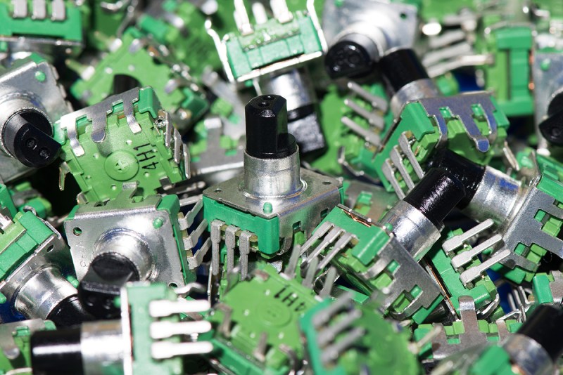
I needed a rotary encoder — I pulled a cheap one out of one of those “49 boards for Arduino” kits you see around. Not the finest encoder in the land, I’m sure, but it should do the job. Unfortunately, Mbed OS doesn’t have a driver for an encoder and the first few third-party libraries I found either worked via polling or wouldn’t compile with the latest Mbed. Of course, reading an encoder isn’t a mysterious process. How hard can it be to write the code yourself? How hard, indeed. I thought I’d share my code and the process of how I got there.
There are many ways you can read a rotary encoder. Some are probably better than my method. Also, these cheap mechanical encoders are terrible. If you were trying to do precision work, you should probably be looking at a different technology like an optical encoder. I mention this because it is nearly impossible to read one of these flawlessly.
So my goal was simple: I wanted something interrupt driven. Most of what I found required you to periodically call some function or set up a timer interrupt. Then they built a state machine to track the encoder. That’s fine, but it means you eat up a lot of processor just to check in on the encoder even if it isn’t moving. The STM32 CPU can easily interrupt with a pin changes, so that’s what I wanted.
The Catch
The problem is, of course, that mechanical switches bounce. So you have to filter that bounce either in hardware or software. I really didn’t want to put in any extra hardware more than a capacitor, so the software would have to handle it.
I also didn’t want to use any more interrupts than absolutely necessary. The Mbed system makes it easy to handle interrupts, but there is a bit of latency. Actually, after it was all over, I measured the latency and it isn’t that bad — I’ll talk about that a little later. Regardless, I had decided to try to use only a pair of interrupts.
In Theory
In theory, reading an encoder is a piece of cake. There are two outputs, we’ll call them A and B. When you turn the knob, these outputs send out pulses. The mechanical arrangement inside is such that when the knob is turning in one direction, pulses from A are 90 degrees ahead of the pulses from B. If you turn the other way, the phase is reversed.
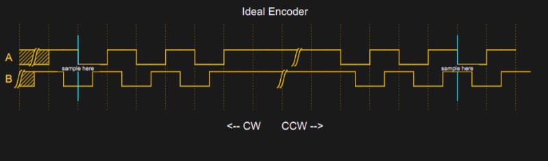
People usually think of the pulses as going positive, but most real encoders will have a contact to ground and a pull up resistor, so actually, the outputs are often high when nothing is happening and the pulses are really low pulses. You can see that in the diagram when no one is turning the knob, there is a long stretch of high signal.
Note on the left side of the diagram that the B signal drops before the A signal every time. If you sample B at the falling edge of A, you will always get a 0 in this case. The width of the pulses depends on the speed you turn, of course. When you turn the other way, you get the case on the right side of the diagram. Here, the A signal goes low first. If you sample at the same point, B is now 1.
Note there is nothing magic about A, B, or the clockwise and counterclockwise labels. All it really means is “one way” and “the other way.” If you don’t like how the encoder is moving you can just swap A and B or swap it in software. I just picked those directions arbitrarily. Usually, channel A is supposed to “lead” in the clockwise direction, but it also depends on the edge you measure and how you connect everything. In software, you generally add one to a count for one direction and subtract for the other direction to get an idea of where you are over time.
There are many ways you can read this sort of input. If you are sampling it, it is pretty easy to build a state machine from the two bits and process it that way. The output forms a gray code so you can throw away bad states and bad state transitions. However, if you are sure about your input signal, it can be much easier than that. Just read B on one edge of A (or vice versa). You could verify the other edge if you wanted a little more robustness.
In Practice
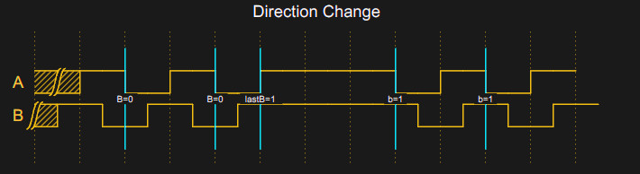
Unfortunately, real mechanical encoders don’t look like the above diagram. They look more like this:


This leads to a problem. If you are interrupting on both edges of input A (the upper trace on the scope), you will get a series of pulses at both edges. Notice that B is in different states at each edge of A, so if you get an even number of pulses in total, your total count will be zero. If you are lucky, you might get an odd number in the right direction. Or you might get the wrong direction. What a mess.
But on the sampling edge of A, B is rock solid. The lower trace on the scope looks like a straight line because all the B transitions are off the screen at that scale. That’s the secret to easily debouncing an encoder. When A is changing, B is stable and vice versa. Since it is a gray code, that makes sense, but it is the insight that makes a simple decoder possible.
The Plan
So the plan is to notice when A goes from high to low and then read B. Then ignore A until B changes. If you want to monitor B, of course, it has the same problem so you have to lock it to A which is stable at the change. In my case, I didn’t want to use two more interrupts so I follow this logic:
- When A falls, record the state of B and update the count. Then set a lock flag
- If A falls again, if the lock flag is set or B has not changed, do nothing.
- When A rises, if B has changed, record the state of B and clear the lock flag.
That means in the scope trace above, the first dip in the top trace causes us to read B. After that, none of the transitions on the screen will have any effect because B has not changed. The rising edge off the screen that occurs after B has had a noisy high to low transition will be the one that unlocks the algorithm.
The Problem
There is a problem, though. The whole scheme relies on the idea that B will be different on a true rising edge for A compared to a falling edge. There is one case where B doesn’t change but we still want to accept the A edge. That’s when you change directions. If you monitored B, that would be easy to solve, but that’s more code and two more interrupts. Instead, I decided that for a person twisting a knob, if you wildly twist in different directions very quickly, you won’t even notice that one or two clicks of the encoder went the wrong way. What you will notice is if you make a fine adjustment and then twist the other way deliberately.
When you think you know the previous state of B and nothing has changed in a while (like a few hundred milliseconds) the code will reset its idea of B to unknown so that the next B signal will be considered valid no matter what.
I used the Kernel::Clock::now feature from Mbed. It isn’t clear if you are supposed to call that from an interrupt service routine (ISR), but I am and it seems to work without problems.
The only other issue is to make sure the count doesn’t change in the middle of reading it. I disabled interrupts around the read just to make sure.
The Code
You can find the code on GitHub. If you made it through all the explanations, you should have no problem following along.
void Encoder::isrRisingA()
{
   int b=BPin; // read B
   if (lock && lastB==b) return; // not time to unlock
// if lock=0 and _lastB==b these two lines do nothing
// but if lock is 1 and/or _lastB!=b then one of them does something
   lock=0;
   lastB=b;
   locktime=Kernel::Clock::now()+locktime0; // even if not locked, timeout the lastB
}

// The falling edge is where we do the count
// Note that if you pause a bit, the lock will expire because otherwise
// we have to monitor B also to know if a change in direction occurred
// It is tempting to try to mutually lock/unlock the ISRs, but in real life
// the edges are followed by a bunch of bounce edges while B is stable
// B will change while A is stable
// So unless you want to also watch B against A, you have to make some
// compromise and this works well enough in practice
void Encoder::isrFallingA()
{
   int b;
   // clear lock if timedout and in either case forget lastB if we haven't seen an edge in a long time
   if (locktime<Kernel::Clock::now())
     {
     lock=0;
     lastB=2; // impossible value so we must read this event
     }
   if (lock) return; // we are locked so done
   b=BPin; // read B
   if (b==lastB) return; // no change in B
   lock=1; // don't read the upcoming bounces
   locktime=Kernel::Clock::now()+locktime0; // set up timeout for lock
   lastB=b; // remember where B is now
   accum+=(b?-1:1); // finally, do the count!
}
Setting up the interrupt is easy because of the InterruptIn class. This is like a DigitalIn object but has a way to attach a function to the rising or falling edge. In this case, we use both.
Latency
I wondered how much time it took to process an interrupt on this setup, so that code is available if you set #define TEST_LATENCY 1. You can see a video of my results, but TLDR: It took no more than 10 microseconds to get an interrupt and often about half of that.
Getting the encoder right was a little harder than I thought it would be, but mostly because I didn’t want to process more interrupts. It would be simple enough to modify the code to watch the B pin relative to the A pin and have a true understanding of the correct state of B. If you try that modification, here’s another idea: by measuring the time between interrupts, you could also get an idea of how fast the encoder is turning, which might be useful for some applications.
If you want a refresher on gray code and some of where it is useful, we’ve talked about it before. If all this sounds oddly familiar, I used an encoder on an old version of Mbed in 2017. In that case, I used a canned library that periodically polled the inputs on a timer interrupt. But like I say, there’s always more than one way to make stuff like this happen.
[Headline image: “Rotary Encoder” by SparkFunElectronics, CC BY 2.0. Awesome.]


The Gray code aspect of encoders means that bouncing doesn’t really matter, as long as you handle the reading correctly.
For interrupt driven approach, read the pin states at beginning of interrupt and compare it against the state you stored at previous interrupt. Ignore the interrupt flags, they are important only for getting into the interrupt. After you have processed the change, store the state you already read to be used next time. By only reading the state once per interrupt, no matter how many edges you have, the total count will be correct – any bounces will just change it +- 1.
On STM32 though, you are best off using the encoder mode on the timers. That avoids any of the interrupt overhead and you can just read a 16-bit count out of the timer count register. It even has hardware filter for the inputs if it seems necessary.
Yeah, on the old Tempest (arcade) spinner they just put A and B into the clock and direction pins on an up/down counter directly. This doesn’t give the full available resolution though. Reading the state of both A and B can give you a 4-count value – use a table of old & new value to get a delta and poll often.
using A and B as clock and direction has the big disadvantage that any noise, bouncing, or just wiggling the knob on the clock edge will cause counting in one direction. With the four state method it’ll just bounce +/-1
The assumption here being pseudo-analog input. If the encoder is being used digitally, like a jog dial running a UI this could get annoying really fast.
I’ve always done this with a 1 kHz timer interrupt and a simple state machine. If ISR takes 1 usec, it only results in 0.1% CPU load. State machine waits for 00->11 or 11->00 transitions, and then checks which bit was the last one to change.
Polling is the sane method indeed. It gives you a predictable system, easier to debug and reason about.
This. Anybody who tries to connect any sort of switch directly to an interrupt pin is in for a world of pain.
Set up a 1kHz interrupt to poll the switch, problem solved.
Putting RC circuits on these cheap mechanical encoders is a common way to tame them.
Don’t just put (ceramic) capacitors on the outputs, as these can deliver very high peak currents (10A+) and can destroy the switch contacts quickly.
Also:
most (all?) STM32 chips have hardware to keep track of the encoder count of quadrature encoders in hardware. You just program it once, and then you read the hardware timer register whenever you feel like doing so. The hardware is built for high speed motor encoders, but it should work on a simple manual knob too.
” Don’t just put (ceramic) capacitors on the outputs, as these can deliver very high peak currents (10A+) and can destroy the switch contacts quickly. ”
10A+, LOL…. Ya maybe if your sticking in a 100uf cap. A simple 200 Ohm on the common pin, and then a 0.1uf-0.2uf cap on its outputs will give you a nice clean transition.
And what do you think happens if you short a 100nF ceramic capacitor by closing the switch?
Such a “nice clean transition” means a high current though the capacitor.
Assume your 100nF ceramic capacitor still behaves as a capacitor upto 100MHz or so.
That means an impedance of 1/(2*pi*100e6*100e-9) = 0.0159 Ohm.
3.3V / 16mOhm = 207A.
… Which means that the current is only limited by ESR, loop inductance and other parasitic effects.
I also (again) had a look at a datasheet of such a rotary encoder, and it has a contact rating of 10mA.
If you want to have some more LOL, then take out your oscilloscope, build up a rotary encoder with a capacitor on it’s output and the normal pullup resistor, and then measure the time in which the capacitor is discharged, and estimate the current from that.
All true but if you’re using the cap as part of a CR filter then there should be a resistor between the switch and cap and the cap straight to the input GPIO.
As in Cap between GND and input
Yes, indeed.
If you look at a datasheet of a bourns rotary, then it has a pullup resistor for each switch, and after the switch a second resistor in the RC filter, and that is the correct way to do it. Tying to eliminate the series resistors of the RC filter and hoping that the pullup resistors are sufficient does not work well.
>capacitor upto 100MHz or so
Your simplistic model is very broken at 100MHz.
Those trace/wire + internal wiring of the encoder + the cap all adds up to huge parasitic inductances which will slow down di/dt. There is a reason why you want short fat traces and small SMT packages for decoupling.
The energy you do get of of the cap is essentially 1/2 C * V^2, but slow down a lot by the parasitic inductance and limited by ESR . i.e. low power over longer period of time.
BTW: at 5V, 1/2 * 0.1E-6 * 5^2 = 0.00000125J of energy.
As for the switch, you might not meet the *minimum* current requirement. This is needed to “blast” off amount of carbon or oxide built up. With the cap, it would actually help.
Also note that maximum current of a switch is usually a factor of I^2 * R heating effects. The duty cycle is so low that it won’t matter.
I am with you about the minimum current (wetting current), but it’s not only I²R it’s also a question of energy (and contact size). So some resistance to limit the current spike to let’s say 50mA or 100mA will prolong the lifetime.
No, not in this case.
These rotary encoders often have a MAXIMUM current specification of only 10mA, so putting 100mA through them as Martin suggest overloads them by a factor of 10.
This contact cleaning current works for contacts that move perpendicular to the contact surface, but these encoders are quite different from that.
Cleaning of the contactacts may rely on the mechanical wiping, or maybe the contacts are coated with silver (Silver does rust, but the black silver oxide is also a good conductor).
Most people are unaware almost all contacts also have a minimum current rating, which if not met allows tarnish to build up and creates unreliable switching after some time.
One common way of meeting this minimum current requirement is the addition of appropriately sized capacitors.
So if you get the capacitor sized right, it helps in multiple ways.
I just built and encoder with 8266 last night and end up with 10k pullups and 0.022uF ceramics to ground. Gives perfect operation, every click increments or decrements by one, no matter how fast or slow the knob is turned.
Capacitors directly across switches are also the/a major cause of the little tact switches failing. This is an extremely common design fault.
When you ask yourself “Why have my washing machine tact switches which are rated 10^6 cycles, failed after 5 years, 5 cycles a week i.e. <2000 cycles"
After a few hundred/thousand cycles, the contact is burned and becomes intermittent. The the user has to push harder to make it work, and then it fails mechanically, because the rated force is quite low, and the user is now exceeding it.
I just did this last night with an ESP8266, 10k pull-up resistors and 0.022 ceramics to ground from each encoder signal yielded gauranteed increment per click, no matter how slow.
Let me see how long this lasts.
From the STM32F411 datasheet:
“TIM2, TIM3, TIM4, TIM5 all have independent DMA request generation. They are capable of handling quadrature (incremental) encoder signals and the digital outputs from 1 to 4 hall-effect sensors.”
The reference manual also gives a tidy example of which registers to set. I’m a huge fan of reading datasheets and using appropriate hardware functions. Good catch.
you don’t need DMA and TIM1 can also do quadrature decoding
I didn’t way they did need DMA, it was just in the quote from the datasheet. Could be useful for an FIR for debounce, though.
Good catch on TIM1, the datasheet doesn’t mention it but the reference manual does.
yep, the STM32F411 I’m guessing he’s using can do at least 4 encoders (maybe 6) using timers
https://github.com/langwadt/nucleo_quad4
Thanks I did not know this. Now I feel bad for torturing my encoders haha.
I have a fancy looking microwave with colour display… but clearly they could have read this, cause the rotary knob only works if you turn it slowly! If it is turned quick it starts jumping backwards instead of forwards. Very annoying
Interesting that it’s bouncing that can cause directional reading problems. I have a guitar pedal, a BOSS DD-20 digital delay, which uses a rotary encoder to set the delay time (either in milliseconds/seconds or by corresponding BPM) which, when I got it, would only adjust upward. That is, if you turned the knob clockwise, the displayed value would increment, but if you turned counterclockwise, the display would decrement once or twice, then start incrementing again. My quick and naive repair was just swapping out that encoder for one I had in my parts bin, which worked fine electrically (the part has the same footprint, but the body is slightly thicker, so the cup that surrounds the knob, letting it be recessed into the front panel, doesn’t fully seat).
I’ve since seen that this is a common failure mode for this pedal — and this probably explains why: mechanical wear in the encoder making it too bouncy for whatever solution the Roland/BOSS engineers picked out back in 2005.
Same on some expensive measurement devices like signal generators.
https://imgur.com/a/dMXEYbj
Clean those contacts!
An HP (Agilent) power supply uses a RPG (Rotary Pulse Generator) to enter parameters (such as Voltage, Current Limit, etc.), This particular unit had been in storage for a while, and exhibited some of the erratic problems you mentioned. Sometimes you could only INCREASE a parameter (but not DECREASE). Some positions of the dial worked fine, but others were erratic.
My reasoning went like this: If the software used a STEP and DIRECTION approach then the “A” signal might be the STEP, and the “B” signal the DIRECTION. If the “B” contacts were dirty or tarnished, then no “B” contact was ever made. So *regardless* of the true dial rotation (CW or CCW), when the “A” contact would signal STEP, the “B” contact would *always* give the same DIRECTION (in this case, CW. i.e. INCREASE).
This was a Bournes RPG module and I anticipated ordering a replacement for only a few dollars., but it was easy to disassemble while still on the PC Board. Cleaning the old caked on dirt and gummed up grease restored clean operation to both the “A” and “B” contacts and returned the power supply unit to correct operation.
In the photo you can see the contact fingers for the “A” and “B” signals, and the spoke pattern on the rotary wheel. Notice the offset between the inner and outer spokes; that’s the phase difference between the “A” and “B”.
Maybe that was deliberately done to keep people from nuking their food and blaming the microwave for their bad cooking? A little behavioral engineering and cost savings rolled up together.
Mine counts only every second detent – also annoying
Some work better with half count, others with full count.
Good encoder libraries supply both options, see the Arduino ones by Erriez for an example, on GitHub.
My mouse’s rotary wheel was behaving in a similarly erratic fashion until i opened it up and used contact cleaner on it. It was a night and day difference in performance.
Keep those switch contacts clean and they’ll reward you.
Contact chatter or bouncing does not go well with interrupts: a big number of interrupts will be triggered in short order during bouncing. This often means the rest of the tasks the MCU has to handle can stall and their throughput is significantly reduced compared to times without contact bounce.
So my suggestion is to use interrupts only to detect an initial change of the inputs. Then disable the input interrupt for some time and change over to a time based solution, for example via virtual times that the RTOS offers. Only when the timer handler doesn’t detect a change for some time you switch back to input interrupts. This way the input interrupts can’t overwhelm the rest of the system.
That’s why I just poll the switches in a timer interrupt. It avoids all this extra complexity. If your system can’t handle a periodic timer, it can’t handle fast bouncing contacts.
The periodic timer interrupt means a constant load. You can’t let your MCU sleep during that time, even if noone is turning the encoder for hours. So using the timer based approach will waste energy which often matters for battery powered applications.
The combination of input interrupt and timer interrupt will solve both problems. But at the cost of higher complexity of course.
Depends. CPU core can sleep while timer is running. For real low power applications, you need the shutdown mode, and then your method wouldn’t work either.
Pin change interrupt still works for lowest power sleep modes. I use it on a power button to wake my projects, my programmer calculator has run off of a cr2032 using this approach for well over a year before I had to replace it. The difference is the cpu doesn’t have to periodically wake just to poll the input and quiescent current in sleep is noticeably lower, it only wakes once the random event occurs. Can make the difference between days or weeks of battery life and upwards of a year. In the end though really what dictates which approach is better is what your specific application is.
Yes, that really makes sense for battery powered applications.
A simple reusable Le software routine to debounce rotary encoders:
https://github.com/naasking/embedded/blob/master/rotary.h
I typically use this within an interrupt routine since it’s so short.
I did some PIC programming in assembly language back before Arduino became a thing. The way I handled reading encoders was an interrupt triggered subroutine with a debounce delay and then a look-up table. The table returned an increment or decrement value. It required minimal code and was super fast and could easily keep up with and speed you could manually spin the encoder. A few more lines of code could make it speed sensitive so the increment/decrement value varied with the speed of encoder rotation.
Here’s basically what you’re describing, but with the bit mask acting as the table to filter out invalid transitions:
https://github.com/naasking/embedded/blob/master/rotary.h
Seems like you could use an interrupt to trigger a timer (and also disable the original interrupt), and then you can use an inactivity algorithm to switch back to the original interrupt (and also disable the timer).
I also had a LOT of trouble with these cheap quadrature mechanical switches, but finally tamed them using a STM32F0 Discovery board Cortex-M0 timer and Forth. I wrote up my project with lots of pics and the full code at:
https://mecrisp-stellaris-folkdoc.sourceforge.io/quadrature-rotary-switch.html
No Interrupts were harmed (or even used) making this project…
Add an RC filter. 0.1uF and 1K are a reasonable place to start.
Run A and B to interrupt on change pins.
in the interrupt:
Read the pins
XOR the new A value to the previous B value.
if zero, add to the position count, if one, subtract from the position count.
Store the B value for the next interrupt.
Exit the interrupt.
Extremely fast
Counts all four transitions per cycle
Very low resource consumption
Someone above mentioned capacitor discharging into the encoder contacts causing issues – Capacitor should be on the microcontroller pin side of the resistor. Discharge current is limited to reasonable values by the resistor.
The time constant of the RC filter does not have to be long enough to cover the entire debounce period. It just needs to be longer than the worst case interrupt latency. Multiple interrupts per transition are a non-issue as long as the interrupt can process them all. They just add and subtract for a net zero change.
For a more detailed explanation of that little xor trick see here: http://www.me.unm.edu/~starr/teaching/me470/quad.pdf
It’s like 8 lines of code and I’ve used it for rotary encoders many times, never had any issues with it. The capacitors are also extremely optional, I never bother with them and it doesn’t have a noticeable impact.
For a more detailed explanation of that little xor trick see here: http://www.me.unm.edu/~starr/teaching/me470/quad.pdf
It amounts to maybe 8 lines of code, and I’ve used it many times for mechanical encoders without any issues. The RC filter is also extremely optional, I never bother with it and it’s never had an adverse affect on performance.
8 lines of code, in a PDF? Couldn’t you just paste them in a comment?
Well no because the PDF is an explanation of how it works, not the code itself. If you just want an example of what it might look like here you go:
volatile uint8_t old_state, position;
ISR()
{
uint8_t new_state = ANY_PIN_REGISTER & 0x03; //assume it’s hooked up to pins 0 and 1
if(new_state == old_state) return;
if((old_state>>1) ^ (new_state & 1)) //xor pin 1 of old state with pin 0 of new state
position++;
else
position–;
old_state = new_state;
}
I usually just put it in a polled interrupt at 100hz or greater.
Hi Rezer, hopefully youre still active on this site! I’ve tried to find the document you mentioned in the link, but it seems to have disappeared off the internet. Is it possible to put it somewhere please so I can download a copy?
Ive tried the code supplied above in C, but I cant get it to work as Id imagine – ie “position” counts up or down when I turn the encoder, and stays static at other times. Im using pins 2 & 3 of port D on a Atmega 328P, so I added a >>1 to put the bits in the rightmost locations ie (PIND & 0b00000110)>>1. Ive tried a variety of sampling frequencies … are there any gotya’s I should be aware of?
I can’t seem to reply to your comment directly Happymacer, so hopefully this still sends some kind of notification. I do happen to have a copy of the PDF, but it’s just a description of how the gray code xor magic works…not sure how much it will help with your current issue. Here’s a link: https://drive.google.com/file/d/1_IThBywVHAetkBwm4puJD_l4IdQv3dd5
What behavior are you seeing?
Beaut thankyou! I get no useful response from the code. Position doesnt increment or decrement as far as Im able to determine. Ive made the AVR turn on a LED when position reaches say 2, and the led will flash during the transition only between position 1 and 2 and back again, but on no other points on the rotation of the encoder. I expected it to stay on at the detents.
How do I log into Hackaday? I cant find a link anywhere!
WooHoo! I think I have it… initialise old_state in the main function in C, then let the timer interrupt read the port and do the logic. (Your code mixes up the logic in the if() statement – swapping old_state and new_state fixes that). Note that Position is updated once for every change in the IO pins, hence moving from 1 detent to the next on a KY40 rotary encoder increments Position by 4, and not by 1 as I had assumed. If I make the LED turn on in multiples of 4 then it illuminates at that detent (eg if Position = 8 the LED turns on at detent 2) and stays on while position remains at that number. Note that Position changes by 4 between detents because the encoder moves between the 4 phases between each detent.
Thanks for the code and your help! Looks like a neat really simple way to read the switch. Ill do some more tests and go from there.
Awesome, glad you got it working…and yeah lots of rotary encoders do transition between states multiple times when moving by a single detent. Can deal with it by increasing the sampling rate or just interrupting on the pin change as the pdf recommends.
A long time ago I found the following code in an electronics magazine.
It perfectly debounces a a single 8 bit register.
unsigned char debounce(unsigned char x)
{
static unsigned char Y1, Y0;
unsigned char y1, y0;
unsigned char z;
y0 = Y0;
y1 = Y1;
Y0 = (y1 & y0) | (x & y0) | (x & y1);
Y1 = x;
z = Y0;
return z;
}
“It perfectly debounces a a single 8 bit register.” is a bit vague.
The code is not obvious, nor that the variables have meaningful names.
Can you explain better how this works?
As best as I can tell it saves the previous IO register state and the previous “debounced” result and compares them with the current register state. Any pins that are 1 in two out of the three are 1 in the result, likewise for 0. Seems a very poor method of debouncing since it’s heavily reliant on polling rate and bounce time, which is completely unpredictable without profiling each individual switch.
There shouldn’t be a problem if you use the correct algorithm. I use one which is not only flawless and self-correctable with any amount of glitches, but also quadruples the resolution, as it does not wait for the whole 360° period to affect the counter. Simply, on any transition of any input you increment or decrement the counter in software, in this way:
Input A: after ANY transition, if inputs are equal, INcrement the counter. If they are different, DEcrement the counter.
Input B: after ANY transition, if inputs are equal, DEcrement the counter. If they are different, INcrement the counter.
I simply XOR both inputs and then XOR the output of the first XOR operation with A input in first case (or B input in second case) after the transition. If you XOR it (for the third time) with the case (0 for A and 1 for B input test), you will have only one routine used by both interrupts and the final result will increment or decrement the counter. And that’s all. I used interrupt-on-change interrupt and switch the edge polarity for that input in every interrupt routine. This works on the project with the low cost mechanical encoder for years and it always returns to zero at the same angle.
The point is that after the glitch passes, the end-of-glitch transition automatically corrects the error caused by the start-of-glitch, so the reading error is never greater than 1. As the resolution is quadrupled, you can use the software discriminator to avoid this reading error elegantly. For instance, to use the second counter which will be incremented or decremented only if there are at least two or three consequent increments or decrements on the first counter.
And about the speed and processor time – that’s why I always use the assembly language routines, at least in critical parts of the software. So the delay is not only short, but highly predictable.
Heh, has anybody ever gotten SAM4N QDEC to work without glitches? I did my time implementing it but there seemed to be missing handling features / state capturing such that one could glitch the decoder. It appeared it were only made for tachometer tasks.
Another fun problem developing in some PSUs seems to be failing rotary encoders… is insufficient bias below wetting current a known issue?
A couple of comments;
1. There’s a Bourns appnote on encoder debounce – a 10nF cap and two 10k resistors, unless you’re incredibly tight on space I’d put the footprints down and if you decide they’re not needed just fit a zero-ohm resistor in one and DNF the other two.
2. STM32’s mostly have encoder modes in their hardware timers/counters, when you want to know the encoder value you just read the counter.
3. I remain unconvinced of the utility of RTOS in any device small enough not to be able to run some variant of Linux, every RTOS example, project, etc. I’ve ever seen has made it look far harder and more bloated than it needs to be, and has not been doing anything that couldn’t be achieved some simpler way.
Some things about denounce:
I remember an old de-bounce circuit (Probably CPU single step) that consisted of a SPDT switch (single pole changeover toggle) that would step when switched down and step when switched up.
The circuit was a SR flip-flop with pull-up resistors on SET and RESET (active low). Ground to the centre of the switch and the two other switch contacts (NO, NC) going to SET and RESET. I won’t bother with the pulse doubler.
It’s bit extreme but it’s inflatable. Why is it infallible? Because the switch has to be switched for there to be contact in the direction it is switched so that first contact can always be trusted – the “bounce” happens AFTER that and the same contact and therefore “bounce” is completely inhibited until the switch makes contact the other way (the trusted event again). So forth.
So you can always “trust” the “FIRST” make of the contacts. The above circuit can work at any speed, far beyond what a human can do. If we limit the requirement to the speeds a human can to then we only need one contact but now only steps on the “ON” direction.
Trust the first switch make contact event (On).
Inhibit any further “On” events for the time calculated to be just less than the humans maximum permissible speed.
After this period of time set to “Off” if the switch is now “Off” (Bounce has ended) and repeat => wait for On event.
No capacitors or resistors though CR networks can save a very small amount of CPU resources and make coding easier.
But there’s more to Quadrature.
I had a Chinesium Quad switch from hell once so this I how I went about the code –
So a state machine that transitions on trusted transitions as described above. Calculate Max speed and use that as polling interval and blame the human if they connect a drill to the switch shaft.
And then the entire missing pulse and this happened often but I was already coding and wasn’t going to swap it out as I had a batch of them and it probably wasn’t the only one.
So now there are even more states to reflect the invalid states from the quad switch. So here’s what I did.
The extra states are –
Missing pulse last going forward.
Missing pulse last going backward.
When the next valid transition indicates the direction, output to counts in that direction and return to a valid state.
You can make it only one pulse and let the wetware work the rest out but none the less you again have a valid direction.
Or better still you could also pot a larger knob on and the wetware downloads LargeScrollerGoSlower and halve the counts from the routine so there is absolutely no external indication that a pulse was missed.
I didn’t have states for missed pulses on both channels at once – that’s the throw it out point.
The problem with a simple RC filter on digital inputs is that the input general has a large indeterminate range. For 3.3 TTL logic this is usually the range from 0.8 volts to 2.1 volts, depending on the part family.
The problem is that you really don’t know what the input will do in that range and if there is any noise the input can lock up in either state. Look for meta-stability.
Usually the amount of time in that range is so small you can safely ignore it. The receiver can’t oscillate fast enough to go metastable.
The fix used in high reliability designs is to use a schmitt trigger between the RC network and the input.
It’s quite common for microcontroller inputs to have schmitt trigger inputs.
I just checked a datasheet of the STM32F103xxxx and it states a hysteresis of 5% of Vdd for the 5V tolerant inputs and 200mV for other inputs.
Also checked an ATmega328, which claims a hysteresis of 50mV.
I once had to read an encoder. In principle I had a piece of code from somebody else, that worked, and my task was to built a few more devices with it. It worked with a nice optical encoder, until I built the second device. Suddenly the second one showed a very strange behavior: It hang with a flickering display. When I slightly moved the knob from the detent, it seemed normal.
It turned out that this type of optical encoder did not have a defined output pattern of “00” when it was at a rest position. It could be any combination of A and B and the state machine did not handle that correct. I treid to use a mechanical encoder like the one in the picture, but the contact bounce made it even worse.
So I decided to rewrite the code for the PIC. I had to do it in polling mode because of my very limited knowledge of C programming. As a HW designer I did (and still do) not know how to use interrupts in C. But it worked and handled all possibilities of the rest position from A/B = 0/0 to 1/1 correctly.
After reading the comments, I think it was a good decision to not use interrupts. With the fixed polling interval the debouncing was no problem and energy consumption was no problem, the device was not battery powered.
I’ve made a digital readout for small precision mills and lathes (Sherline) for about 20 years. It runs on a mini 8051 at 1 MIPS in 2k of code. It reads out three (x,y,z axes ) in absolute real time and maintains a tach display. The encoders are 100 step/R – 25 tooth injection molded units that are built in house very economically. It can readout >5 turns per seconds on all three axes and never ever misses a step- a disaster in a position readout. It also does backlash correction arithmetic, metric conversions and formats and displays the values on a LCD display at this rate. It is polled without any timers or interrupts. The weak link in the chain is how fast the lcd will take the data and the metric conversion math but it all gets done. The very best way to do quad encoding is in dedicated hardware like your ARM has, you can also implement good logic in a small FPGA (even the small SiLego’s with do one channel). Interrupts are the first thing a lot of people think about in these cases but don’t scale well. A reasonable solution as someone above mentioned is a 1 mS tick and then polling- pretty robust there
When I hook mechanical switches up to the scope, typically all that is needed to negate bounce as a concern is a small capacitor.
The problem isn’t that mechanical switches bounce. The problem is that transistors trigger unpredictably within a small range of the input unless the rise/fall slope is similar to the activation slope, and it takes significant effort (or parts) to overcome that.
In my experience, understanding this aspect of the problem can really reduce the number of dead ends and rabbit holes you wander down while trying to “debounce.” Once you fully accept that bounce is mostly an A/D problem, and the implications involved, then when you go straight to fixing that part, you’ll find that now you’re also resistant to the rare case of mechanical bounce.
Have you never heard of analogue filtering? It is always easier to sample digitally if you can clean it up a bit first. Even SPxT switches usually have an RC filter in the order of one Tau of 1ms. Or the typical 10K/100n or 100K/10n for one Tau of 1.6ms.
Have a bag of small cheapies looks very familiar to the post, at first thought they had a chip but, turns out very basic mechanical. Got these for a new project with an attiny soon, recall from oldie days 1984 used a 68705P3 to handle a clean optical encoder with the optical output fed through an RC state change & 74hc86 which fed 4 bits into the CPU port finishing the Inc or Dec instruction, worked very fast though no need for debounce unlike mechanicals…
So comments useful, good post too, thanks to all.
I read this article than I had a classic lightbulb sparking moment.
What if instead of processing the raise and fall of each pin, we process only the raise in an alternate fashion?
When pinA goes HIGH and if we were waiting for it to go HIGH, we set the next raise to process to be for PinB and viceversa.
The other pin status gives you the direction of the knob rotation.
Example:
A raises. Set to wait for B to raise
B raises. If A is still high it’s CW, if A went back to low the movement is CCW. Set to wait for A to raise now.
A raises. If B is still high it’s CCW, if B went back to low than it’s CW.
I tested the idea and it works.
https://gist.github.com/aovestdipaperino/35257c14a29de7d10460f3ed02ce5e14