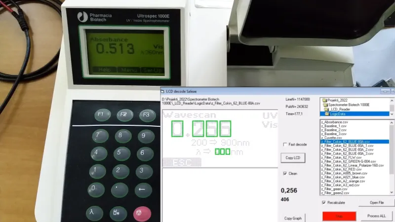
[Jure Spiler] was at a flea market and got himself a spectrophotometer — a device that measures absorbance and transmittance of light at different wavelengths. This particular model seems to be about 25 years old, and it’s controlled by a built-in keyboard and uses a graphical LCD to display collected data. That might have been acceptable when it was made, but it wasn’t enough for [Jure]. Since he wanted to plot the spectrophotometry data and be able to save it into a CSV file, hacking ensued.
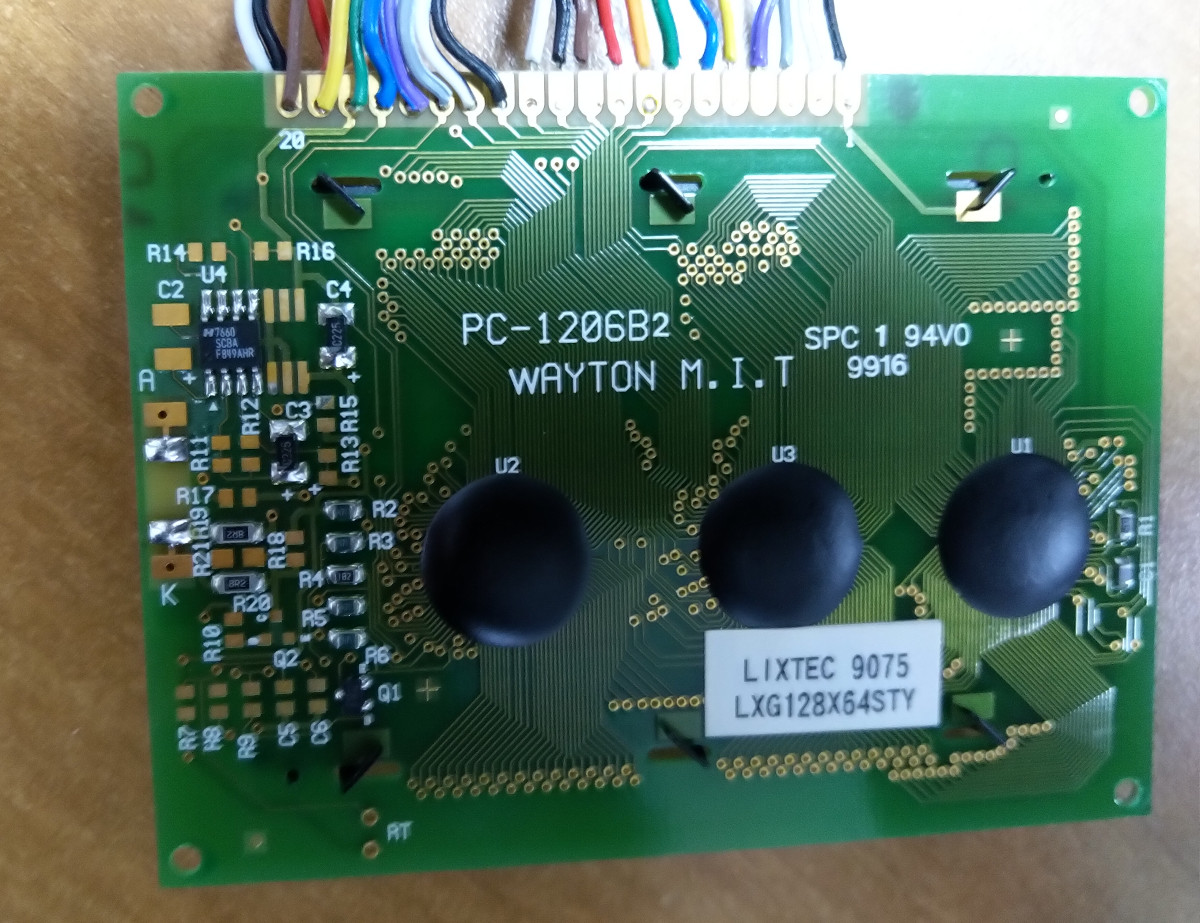
He decided to tap into the the display communication lines. This 128×64 graphical display, PC-1206B, uses a 8-bit interface, so with a 16-channel logic analyzer, he could see the data being sent to the display. He even wrote decoder software – taking CSV files from the logic analyzer and using primitive optical recognition on the decoded pixels to determine the digits being shown, and drawing a nice wavelength to absorbance graph. From there, he set out to make a standalone device sniffing the data bus and creating a stream of data he could send to a computer for storage and processing.
 [Jure] stumbled into a roadblock, however, when he tried to use an Arduino for this task. Even using a sped-up GPIO library (as opposed to notoriously inefficient
 digitalRead), he couldn’t get a readout frequency higher than 80 KHz – with the required IO readout rate deemed as 1 MHz, something else would be called for. We do wonder if something like RP2040 with its PIO machinery would be better for making such captures.
At that point, however, he found out that there’s undocumented serial output on one of the pins of the spectrophotometer’s expansion port, and is currently investigating that, having shelved the LCD sniffing direction. Nevertheless, this serves as yet another example for us, for those times when an LCD connection is all that we can make use of.
We’ve seen hackers sniff LCD interfaces to get data from reflow ovens, take screenshots from Game Boys and even equip them with HDMI and VGA ports afterwards. With a skill like this, you can even give a new life to a vintage calculator with a decayed display! Got an LCD-equipped device but unsure about which specific controller it uses? We’ve talked about that!


I love the use of Visual Basic 6 in 2022. It’s super old and outdated by todays standards, but it just works :D
Never since then have I built GUIs easier and more “native” than with VB 6.0.
What a team of webdevelopers can maybe achieve in half a yrar could be clicked together on an afternoon!
It was stupid easy back then, wasn’t it? I loved VB for all sorts of stuff. Slow, yeah, but you could bang GUIs together so easily, and they control arrays, oh man, talk about awesome.
Ostensibly there is a new https://www.radbasic.dev/ VB6 compatible language
The arduino Due would probably be quick enough and if you dive into the mcu datasheet you’ll probably find a parallel port that can be configured to receive the bus data using a peripheral that can operate independently from the cpu using dma channels. Or you could use a teensy 4.x which surely can do it as would the Pico.
The serial port would be ideal though, you’re probably better able to find out the mode it’s in etc without having to scan for pixels etc.
Thanks for this information. I was not aware of Teensy 4, that semms to be “much faster Arduino”.
As mentioned in my original article, I found another way (serial communication on parallel connector) to get data from the device.
Funny you should have this topic. I built an Arduino to read the serial data between my old hardline burglar/fire alarm and its control panel. I can now get SMS alerts and review the logs on the web.
I came here to read this because that’s what I’m hoping to do. Did you document this? The way my alarm is configured I will need 6 konnected devices to replace the working (dumb) 32 zone system.
Wow, 1MHz readout was impossible with Arduino? Most of Arduino boards I saw had 16MHz quartz. It should do with this task, you have 16 clock cycles between each read. And read of one 8bit port takes one instruction, moving it to ram takes another one. How frequently LCD is feeding with new frame? How many frames has the same data? It should be possible to analyze all incoming information and send out converted value to computer before change in LCD frame.
Don’t forget peoples usualy use Arduino functions, so lot of overhead (pin number to register mapping, pin number to bit mask, “null check” on mapping result, reading register, applying mask to register, return, using result)
Then, the also need to call the same function PER BIT.
We are far away from the read registry, mask everything we need (hopefuly every bit we need is in the same register), using result (where the overhead here may be done at compilation time)
I need to read 13bits (lines) so I tried this IO_Port_16bit.h:
https://create.arduino.cc/projecthub/ambhatt/turn-your-arduino-board-into-16-bit-io-port-ec31ab
On top of reading ports, I need to build local copy of LCD matrix, before sending it to USB.
I discovvered that pollong (loop) is much faster than interrupt (extra 56 cycles).
As mentioned in previous post [imqqmi] teensy 4 would probbaby be a way to go.
As mentioned in my original article, I found another way (serial communication on parallel connector) to get data from the device.
i understand and respect that everyone comes to projects from where they are. not everyone brings every skill (or equipment, for that matter) that would be handy for a project. and that’s beautiful and wonderful and i want to encourage it.
but just from my own emotional-aesthetic perspective, this project seems to really exemplify why i don’t care for arduino. he’s reading a strobe line that’s high for 5us at a time, so he figures he needs to sample at a somewhat higher rate than that in order to be assured of catching it while it’s high. that’s sensible from a certain perspective but it’s also — as he discovers — not really plausible when you’re writing in C++ for an embedded processor.
it’s possible a proper attitude towards embedded development (at least when the goal is just interfacing) would have left him just as high and dry. i just find that hard to believe when he’s started out with so many severe and unnecessary disadvantages.
it doesn’t hardly matter. it just makes me sad when i see hardware that’s capable of a task, but is handicapped by software. because of arduino, he was given relatively easy access to an incredibly powerful platform, but then it turns out that he is being teased, most of the power was taken away before he got to it.
Yes indeed let’s paint the entire embedded development space with one big broad brush and dismiss it all as garbage because someone decided to use polling instead of an interrupt.
The arduino environment allows you to read directly from the ports using special “variables”, these come from the AVR headers (or just write your own assembly – the C++ should compile to something as fast though). The speed is 1 clock cycle = 1 instruction.
yeah i mean you can bypass any of the arduino conveniences and you’re left with basically a decent avr board. but that’s why i’m talking about this particular example — Jure specifically did not do that, because that wasn’t what was on his mind. when he noticed that one C++ I/O wrapper library was too slow, he switched to another one. it was much better but still too slow or inflexible for his purposes. maybe it could have been made to work even without writing any ASM but the path he followed didn’t lead him there. it’s not proof that arduino is bad, and it’s not really a slight against him either. it’s just an example of the sort of journey that is pretty typical — though wholely avoidable — once this path is selected.
personally, i started working on the problem from the logic analyzer trace screenshot on his project page. and right away, i want to know how many microseconds between the data transition and the two edges of the data-enable strobe line. and then i want to look in the microcontroller datasheet…since i’m a PIC12 guy by habit, i can see a busy loop implementation using MOVF MOVF BTFSS GOTO, and i can sum up the clock cycles of that and figure out whether the busy loop implementation is plausible. or i can look at the cycles of a GPIO-triggered ISR branch then MOVF MOVF. the trace wasn’t detailed enough for me to come to any conclusions but it looks to me like both approaches are plausible and probably the same is true on ATmega.
my point is, i do know how to solve the problem but i don’t know how to do it without knowing the assembly instructions. but arduino’s whole advantage is that you won’t have to do that. even if the compiler does a very good job, i wouldn’t trust it to pick the right sequence…even if it works for me, i would expect that a future version of the same compiler might (essentially stochastically) chose a different sequence which is too slow. i work in compilers so i know that kind of thing is very common in inner loops, and hardly anyone cares…except on embedded when your instruction timing is directly related to your I/O characteristics.
This would be a perfect project to use a camera to grab the data from the display – Use Open CV and export to CSV without having to open and solder anything to it.
To be honest, I saw the picture and thought they did exactly that ;)
I was thinking the same. Lets you keep the project portable across different tools / LCD panels. Cheer!
I have done the same for an old alarm system with 4×20 hd44780.
MQTT the alarm status and such.
Works a treat..
How does one identify the panel?
Alot of text displays are “HD88780” protocol compatible.
Did you document how to do this?
The Ultrospec 1000 serial port is not difficult to identify by having a close look at the PCB. Hook up an oscilloscope, turn the serial output on in the settings, record spectra for continuous output and off you go. I have constructed a USB adapter for this instrument a few years ago, which allows recording data and talking to the instrument by using any simple terminal emulator.
I’d like to discuss your experinece a little further.
Where did you publish it?
I managed to read serial data from PIN1 of parallel connector and
made a suitable software to collect, display, compare spectrums.
I am not aware of “sending commnads” to Ultrospec 1000.
I’ve seen LCD sniffing used as a way to add text to speech for visually impaired user’s accessibility needs, there was a compnay making retrofit adapters at one point
oh that sounds wonderful! I’d be delighted to know more about this!
Me too!