As one of the most popular buses today for on- and inter-board communication within systems, there’s a good chance you’ll end up using it with an embedded system. I2C offers a variety of speeds while requiring only two wires (clock and data), which makes it significantly easier to handle than alternatives, such as SPI. Within the STM32 family of MCUs, you will find at least one I2C peripheral on each device.
As a shared, half-duplex medium, I2C uses a rather straightforward call-and-response design, where one device controls the clock, and other devices simply wait and listen until their fixed address is sent on the I2C bus. While configuring an STM32 I2C peripheral entails a few steps, it is quite painless to use afterwards, as we will see in this article.
Basic Steps
Assuming that the receiving devices like sensors are wired up properly with the requisite pull-up resistors in place, next we can begin to configure the MCU’s I2C peripheral. We’ll be using the STM32F042 as the target MCU, but other STM32 families are rather similar from an I2C perspective. We’ll also use CMSIS-style peripheral and register references.
First, we set the GPIO pins we wish to use for the I2C peripheral, enabling the appropriate alternate function (AF) mode. This is documented in the datasheet for the target MCU. For the STM23F042 MCU, the standard SCL (clock) pin is on PA11, with AF 5. SDA (data) is found on PA12, with the same AF. For this we need to set the appropriate bits in the GPIO_AFRH (alternate function register high) register:
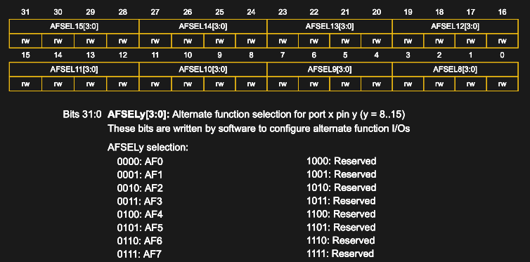
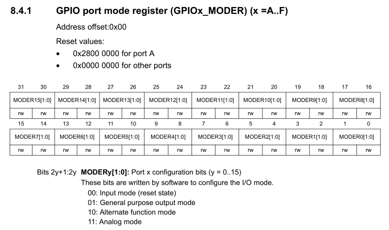
By selecting AF 5 for pins 11 & 12 (AFSEL11 & AFSEL12), these pins are then connected internally to the first I2C peripheral (I2C1). This is similar to what we did in a previous article on the UART. We also have to enable AF mode for the pin in GPIO_MODER:
All of this is done using the following code:
uint8_t pin = 11;                // Repeat for pin 12
uint8_t pin2 = pin * 2;
GPIOA->MODER &= ~(0x3 << pin2);
GPIOA->MODER |= (0x2 << pin2);   // Set AF mode.

// Set AF mode in appropriate (high/low) register.
if (pin < 8) {
    uint8_t pin4 = pin * 4;
    GPIOA->AFR[0] &= ~(0xF << pin4);
    GPIOA->AFR[0] |= (af << pin4);
}
else {
    uint8_t pin4 = (pin - 8) * 4;
    GPIOA->AFR[1] &= ~(0xF << pin4);
    GPIOA->AFR[1] |= (af << pin4);
}
Note that we want the SCL and SDA pins to be both configured in the GPIO registers to be in a floating state without pullup or pulldown, and in open drain configuration. This matches the properties of the I2C bus, which is designed to be open drain. Effectively this means that the pull-ups on the bus lines keep the signal high, unless pulled down by a master or slave device on the bus.
The clock for the first I2C peripheral is enabled in RCC_APB1ENR (enable register) with:
RCC->APB1ENR |= RCC_APB1ENR_I2C1EN;
Some STM32F0 MCUs have only a single I2C peripheral (STM32F03x and F04x), while the others have two. Regardless, if the I2C peripheral exists, after setting its clock enable bit in this register, we can now move on to configuring the I2C peripheral itself as a master.
Clock Configuration
Before we do anything else with the I2C peripheral, we must make sure that it is in a disabled state:
I2C1->CR1 &= ~I2C_CR1_PE;
The clock settings are set in I2C_ TIMINGR:
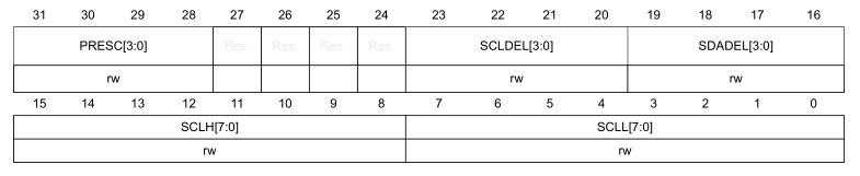
The reference manual lists a number of tables with timing settings, depending on the I2C clock, e.g. for a 8 MHz I2C clock speed on STM32F0:
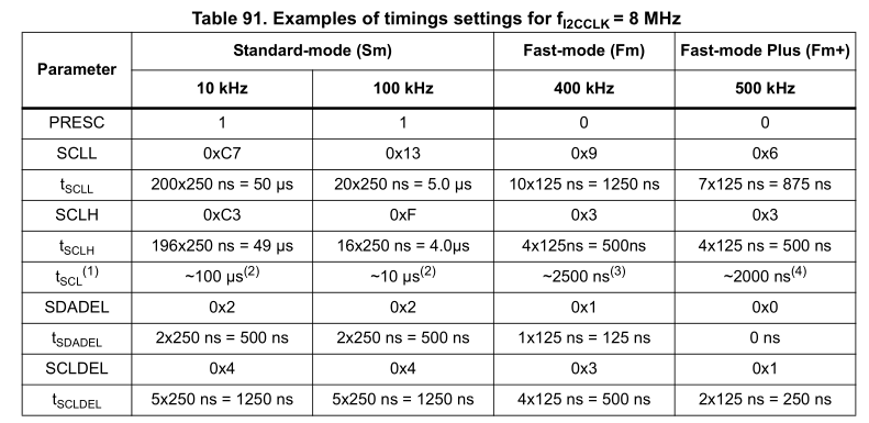
This table can be converted into a ready-to-use array of values to configure the I2C peripheral with by putting these values into the right order for insertion into I2C_TIMINGR, e.g. for STM32F0:
uint32_t i2c_timings_4[4];
uint32_t i2c_timings_8[4];
uint32_t i2c_timings_16[4];
uint32_t i2c_timings_48[4];
uint32_t i2c_timings_54[4];

i2c_timings_4[0] = 0x004091F3;
i2c_timings_4[1] = 0x00400D10;
i2c_timings_4[2] = 0x00100002;
i2c_timings_4[3] = 0x00000001;
i2c_timings_8[0] = 0x1042C3C7;
i2c_timings_8[1] = 0x10420F13;
i2c_timings_8[2] = 0x00310309;
i2c_timings_8[3] = 0x00100306;
i2c_timings_16[0] = 0x3042C3C7;
i2c_timings_16[1] = 0x30420F13;
i2c_timings_16[2] = 0x10320309;
i2c_timings_16[3] = 0x00200204;
i2c_timings_48[0] = 0xB042C3C7;
i2c_timings_48[1] = 0xB0420F13;
i2c_timings_48[2] = 0x50330309;
i2c_timings_48[3] = 0x50100103;
i2c_timings_54[0] = 0xD0417BFF;
i2c_timings_54[1] = 0x40D32A31;
i2c_timings_54[2] = 0x10A60D20;
i2c_timings_54[3] = 0x00900916;
The other options available here are to let the STMicroelectronic-provided tools (e.g. CubeMX) calculate the values for you, or to use the information in the reference manual to calculate it yourself. At this point in time, the Nodate framework I2C implementation for STM32 uses both, with the predefined values as above for STM32F0, and dynamically calculated values for other families.
The advantage of dynamically calculating the timing values is that it doesn’t rely on predefined I2C clock speeds. As a disadvantage there is the additional delay involved in calculating these values, rather than reading them directly out of a table. Whichever approach works best likely depends on the project’s requirements.
With the I2C_TIMINGR register thus configured, we can enable the peripheral:
I2C1->CR1 |= I2C_CR1_PE;
Writing Data
With the I2C peripheral ready and waiting, we can begin to send data. Much like with a USART, this is done by writing into a transmission (TX) register and waiting for the transmission to complete. The steps to following here are covered in the helpful flow diagram provided in the reference manual:
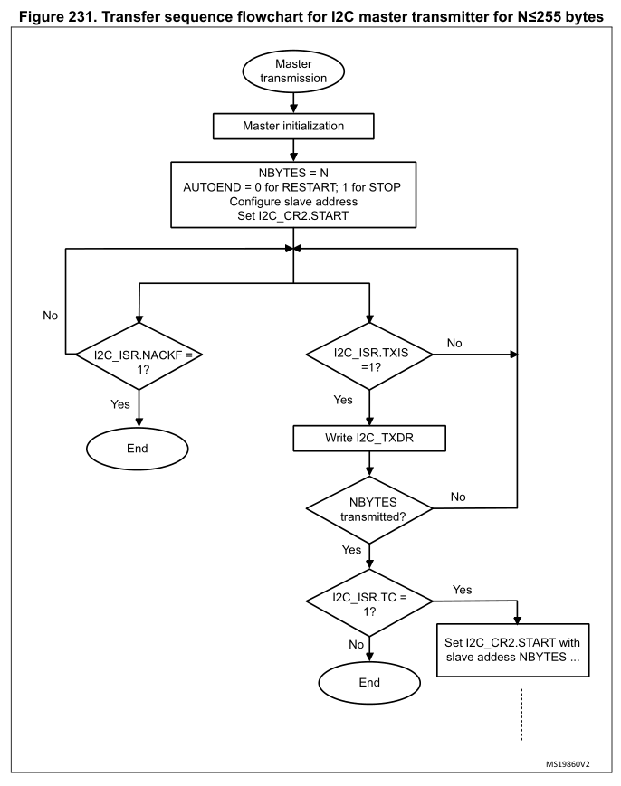
Worthy of note here is that with some checks, such as for I2C_ISR_TC (transfer complete), the idea is not to check once and be done, but rather to wait with a time-out.
For a simple transfer of 1 byte, we would set I2C_CR2 as such:
I2C1->CR2 |= (slaveID << 1) | I2C_CR2_AUTOEND | (uint32_t) (1 << 16) | I2C_CR2_START;
This would start the transfer for a total of 1 byte (left-shifted to the NBYTES position in the I2C_CR2 register), targeting the 7-bit slaveID, with the I2C stop condition auto-generated. After the transfer is done (NBYTES transferred), the STOP is generated, which sets a flag in I2C_ISR called STOPF.
When we know we are done with transferring data, we must wait for this flag to be set, followed by clearing the flag in I2C_ICR and clearing the I2C_CR2 register:
instance.regs->ICR |= I2C_ICR_STOPCF;
instance.regs->CR2 = 0x0;
This completes a basic data transfer. For transferring more than a single byte, simply loop the same procedure, writing a single byte into I2C_TXDR each cycle and waiting for I2C_ISR_TXIS to be set (with requisite time-out). To transfer more than 255 bytes, setting I2C_CR2_RELOAD instead of I2C_CR2_AUTOEND in I2C_CR2 will allow for a new batch of 255 bytes or less to be transferred.
Reading Data
When reading data from a device, be sure that interrupts are disabled (using NVIC_DisableIRQ). Generally, a read request is sent to the device by the microcontroller, with the device responding by sending the requested register contents as reply. For example, if a BME280 MEMS sensor is sent 0xd0 as only payload, it will respond by sending back its (fixed) ID as programmed into that register at the factory.
The basic flowchart for receiving from a device looks as follows:
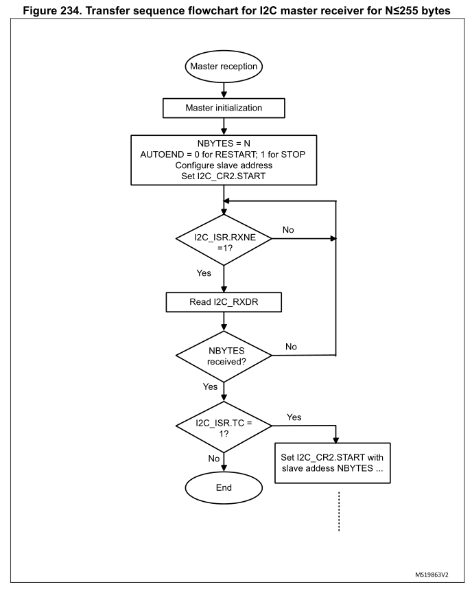
The basic idea here is the same as with transmitting data. We configure I2C_CR2 in the same manner as before. Main differences here are that we wait for the I2C_ISR_RXNE flag to become unset, after which we can read the single-byte contents of I2C_RXDR into our buffer.
Just like with writing data, after we read NBYTES, we have to wait for the I2C_ISR_STOPF flag to be set, followed by us clearing it via the I2C_ICR register and clearing the I2C_CR2 register.
Interrupt-based Reads
Setting up interrupts with I2C requires us to activate the interrupts for the I2C peripheral in question. This must be done with the peripheral in a disabled state. After this we can enable the interrupt:
NVIC_SetPriority(I2C1_IRQn, 0);
NVIC_EnableIRQ(I2C1_IRQn);
Interrupts are then enabled on the peripheral by setting the configuration bit:
I2C1->CR1 |= I2C_CR1_RXIE;
Ensure that the appropriately named interrupt handler (ISR) is implemented with the name as specified in the boot-up code:
volatile uint8_t i2c_rxb = 0;

void I2C1_IRQHandler(void) {
    // Verify interrupt status.
    if ((I2C->ISR & I2C_ISR_RXNE) == I2C_ISR_RXNE) {
        // Read byte (which clears RXNE flag).
        i2c_rxb = instance.regs->RXDR;
    }
}
Don’t forget to add the extern "C" { } block around the handler if using a language other than C to prevent function name mangling.
With this code in place, every time the read buffer receives a byte, the ISR will be called and we can copy it into a buffer, or somewhere else.
Multi-Device Usage
As can be surmised at this point, using multiple devices from a single microcontroller transceiver only requires that the correct device identifier is sent before any payload. This is also where clearing the I2C_CR2 register and correctly setting it the next transmit or receive cycle is essential, to prevent any mix-up in device identifiers.
Depending on the code implementation (e.g. with a multi-threaded RTOS), it’s possible that conflicting reads and writes could take place. It’s essential in this case that I2C writes and reads are coordinated so that no data or commands are lost, or sent to the wrong device.
Wrapping up
Using I2C on STM32 is not very complicated, once one clears the hurdle of setting up the clock configuration. That is a topic which may be worthy of its own article, along with advanced topics pertaining to I2C such as clock stretching and noise filtering. By default the I2C peripheral on STM32 MCUs has a noise filter enabled on its I2C inputs, but these can be further configured as well.
As easy as basic reading and writing is with I2C, there is still a whole rabbit hole to explore, also when it comes to implementing your own I2C device on STM32. Stay tuned for further articles on these topics.


Is anybody using a Bus Pirate to talk to I2C devices like this anymore?
“uint8_t pin2 = pin * 2;” This is a good example of someone who doesn’t understand coding to well.
Just put the stinking number directly in there.
My guess is the typical copy-paste-modify operation which introduces a large percentage of new and hitherto unseen bugs (or at the very least strange looking code e.g. https://twitter.com/id_aa_carmack/status/978639557515083776 ).
My guess was that they did mean to type 12, but were low on coffee or distracted.
Reminds me of this: 1:01:10 in the keynote talk at quakecon 2011 ( https://www.youtube.com/watch?v=4zgYG-_ha28#t=1h01m10s )
A transcript of from the linked video above is at: https://www.shamusyoung.com/twentysidedtale/?p=12574
John Carmack talks about a particular kind of bug that creeps into software ‘Most software bugs come from copy & pasting code.’ … ‘The problem with copy-paste code is that it is, by its very nature, code that already compiles. If I accidentally fat-finger type “neq_position” instead of “new_position”, it won’t compile and I’ll fix the problem right away. But by copying selections of working code you can omit error checking, leave variables unchanged, accidentally perpetrate variable name collisions (where the same variable is used to two totally different things) or leave out proper memory management steps – all of which are things you’re unlikely to do if you’re forced to type out each line.’
Actually no, it’s the other way around. This is an example of someone who DOES understand the coding — just putting the raw number in there is what you’d expect from a junior programmer without much experience.
See, the compiler will optimize the second variable out of the code at compile time, so the machine code produced will be exactly the same either way. But writing it like this shows the *intent*, which is absolutely critical if you expect someone to actually read your code.
In this case, the pin is number 11, but since there are two bits per pin, the offset you have to modify is located at double the pin number. This fact is captured clearly and cleanly in the code above. If they’d hardcoded “22” instead, then you’d have to document somewhere how you got that number, which is always a worse choice since code is (by definition) up-to-date while comments tend to get stale. You should write your code to document itself whenever possible, and this is an excellent example of doing exactly that.
If you wanted to set pin 12 instead of pin 11, then how you get there is trivially clear: just change the 11 to a 12. No math necessary, no mistakes possible.
Probably an engineer and not someone with a background in computer science. Since I have a degree in the latter and 30 years of experience I can confirm what you said. It’s the intent that counts and it should reflect that in the code. I have to deal with engineers who have such a narrow mindset on a regular basis. ;-)
Look at errata of i2c, it’s always FULL OF bugs, use bitbang
You can get burned with all types of peripherals an features of microcontrollers. May I suggest using pen and paper for calculations, and automatons for everything else?
Perhaps it also takes starting on devices like ATTiny2313 and avr asm to appreciate the feature-rich efficiency of STM32 peripherals, up to and including DMA.
I prefer seeing my code screw around in FreeRTOS tasks that do something useful, like updating displays and processing network traffic, as opposed to watching bit-paint dry. Treat yourself to a challenge where you cannot afford to be muckin’ around with bit-banging. See how you like it.
Look at errata for everything on stm32, full of bugs. Maybe try nxp or atmel, oops still full of bugs. How about Intel or AMD? Aren’t they the best? Nope, still full of bugs. Gosh is it really true that none of this stuff actually works? Those ST I2C demos, they are all fraud? Who knew?
Yes here at hackaday we all use perfect things and we never have to work around hardware issues.
Your ARM uC is literally throwing away hundred of clock cycle just to bitbang at 400kHz! You might as well use an 8-bitter running at 8MHz. There are features that is very messy for bit-banging code e.g. clock stretching, peripheral mode etc. Who is to say that you won’t introduce bugs in your code?
At least now that the I2C patent is over. There were a lot of patent suits against other manufacturers towards the end of the patent. I2C is not exactly my preferred interface (if I have a choice) as it is too clunky requiring a lot of firmware interactions (i.e.not DMA friendly)
There are errata, but there are ST work arounds. They would have to ditch/fix/license the I2C peripheral otherwise. Chances are that there are specific app. notes covering that topic.
I2C is especially clunky when your CPU resets in the middle of a transfer, and the client is still holding SDA low.
Not every I2C peripheral comes with the appropriate reset circuitry to get the bus back into the idle state.
Generally, generation a couple of stop events will clear the bus, but that does require all slave devices de de-assert the SDA line. If SDA is stuck low indefinitely, you’re out of luck.
I generally try to avoid I2C (in favor of SPI), or make sure the microcontroller has the possibility to reset all devices, either with a shared reset pin, or by cycling the power to them.
“Not every I2C peripheral comes with the appropriate reset circuitry to get the bus back into the idle state.”
I’d love to see one that does come with the appropriate reset circuitry, considering there isn’t one. The only ‘foolproof’ way to get the bus back to idle is a hardware reset or power cycle. That’s literally in the I2C specification.
The only reset mechanism actually even mentioned is just the whole “send 9 clock pulses” bit which you can just bit-bang right at power on before switching them to I2C.
Most of my I2C peripherals don’t have a hardware reset. Some can’t even be power cycled under CPU control. Trying to send some clocks until SDA goes up, and then performing a stop condition is often the only reasonable option left (it usually works).
Sending up to 9 clock pulses is something that can be easily done in the hardware peripheral. If I’m going to bit bang that procedure, I’ve already done most of the work to bit bang the entire protocol.
“If I’m going to bit bang that procedure, I’ve already done most of the work to bit bang the entire protocol.”
You and I have very different definitions of “work.”
while( not sda ) do set_pin(scl, low), delay(1 ms), set_pin(scl, high).
That’s not even remotely close to fully bitbanging I2C. You never even set SDA here!
The way I handled it was to configure the I2C as GPIO pins, then push out 9 clocks.
heh i still cringe every time i see C in a “bare metal microcontroller” sort of article. C is great. C is my life. but on microcontrollers, even on the powerful STM32, if i’m doing “bare metal”, if my main goal is I/O interfacing and not complicated program logic, then i am using ASM or the thinnest bespoke wrapper around ASM.
i guess this dovetails with the Viktor comment to use bitbang. i’ve never used real i2c in one of my own projects, but i’ve used a few pidgin-i2c buses at different times, and dallas one-wire, and so on, and i always bitbang. i like knowing what’s going on. bitbanging is one of those things where ASM on a microcontroller really outshines C. you can count the cycles, man!
> i like knowing what’s going on
there’s knowing the inner workings, but there is also knowing one’s way around debugging on that level. In my personal opinion, a lot speaks for living with hardware abstraction but still allowing room for, let’s say, explorations of the deeper inner workings (outside debugging code right before a deadline :) ).
Perhaps there is also still too little awareness of just how powerful microcontrollers get when moving from lower-end microcontrollers to STM32F4, STM32F7 or H7. The posterchild of applications that practically use goodies like DMA, instruction and data caches and high troughput memory interfaces is video.
Check out this 3-part series:
https://openmv.io/blogs/news/the-path-to-performance-part-1
You can’t really count the exact cycles if you have interrupts or caches/accelerators or multiple AHB masters.
Fairly easy to bitbang I2C in C, because it’s so slow. You can poll a free running timer to create the minimum delays.
I wouldn’t consider 400kHz or 1MHz slow enough for bitbanging. Also, why would you? Do you really think you can do a better job than an army or STM hardware engineers?
Sure the can be or two silicon bugs, but those are generally fairly easy to work around, and your bitbang code is bound to have a few bugs, too.
Bitbanging is incredibly wasteful; if you have CPU time for that, you’ve used a massively overkill CPU, that’s much more expensive than it needs to be for the job at hand.
I can’t imagine any company allowing you to do that (or asm just because “you want to”), especially for any medium to large scale production, where several euros/dollars extra for the faster CPU is going to be a serious issue.
For pretty much all my projects, the overhead for bit banging is low enough that it doesn’t cause any problems, so why should my company not allow it? The company cares about development time, and that’s usually lower with a bit banging solution, because the code is more portable, and mostly debugged.
Manufacturers have a wide range of ideas on how to make I2C peripherals, so it’s almost never an easy task, especially not if you want to run the whole thing in an interrupt driven state machine.
most of the bitbanging i’ve done is on a PIC12s, so i don’t think the waste has to cost anything. sometimes it’s necessary to bitbang, and sometimes it’s necessary to make really intricate use of the timer/counter units, or so on. sometimes i bitbang from a timer ISR and sometimes i do it from a busy loop…sometimes even the logic is in the ISR and the real time component is in the main loop. sometimes you might even need a little external 74xx series chip to meet all the requirements of the project. it all depends.
i’m not opposed to using onboard peripherals but usually when i embark on an embedded project i take an inventory of the I/O systems it has and then try to fit those to my requirements and if i see an obvious way to make it work within the resources available then i stop looking, and as a result i haven’t actually used an on-chip UART since my 8051 days. mostly because i don’t want a standard serial protocol i want something ridiculously target specific (iow, because the rest of my circuit is a dumb hack instead of a standard-conforming I2C device).
as for asm, you tell me in one moment that they are tremendously cost-conscious and the next that they’d demand a high-level development environment. i’m sure in real life you’ll find examples all along that spectrum, including both at once. but here’s the thing, i’m just criticizing the use of ‘bare metal’ to describe ‘with a compiled language’. not all projects need to be bare metal, just the bare metal ones do.
wow, i had no idea there are stm32s with cache! i’ve always used the STM32F100 series, which has no cache. as far as interrupts being unpredictable, it can be true but i really like that i can count how many cycles the ISR takes. i may not know when the asynchronous event will happen but i will know exactly when the chip responds to it. when i’m programming asm, i always know exactly which interrupts are in play. it is surely possible to understand a language runtime library well enough to say the same in C, but when i’m doing “bare metal” i’m glad i don’t have to learn about any mistakes i didn’t have to.
There are quite a few STM32s (and other similar CPUs from other brands) it’s a mini cache which they call a ‘flash accelerator’ or ‘flash buffer’. It’s a little bit of SRAM that acts like a cache between the CPU and the Flash interface. If your code happens to be in that buffer, it runs without delay, otherwise it can take a number of extra wait states. For really time critical code, it is possible to copy the function into fast SRAM at startup so you avoid that uncertainty and extra delay.
This code made me think I should continue my c++ header files (zero overhead) for blue pill. So much readable code and comfort.
*this*
Have you tried reading other people’s readable C++ code? I always find it’s a struggle to figure out where they’ve hidden all the things that happen under the hood.
“The advantage of dynamically calculating the timing values is that it doesn’t rely on predefined I2C clock speeds. As a disadvantage there is the additional delay involved in calculating these values, rather than reading them directly out of a table. Whichever approach works best likely depends on the project’s requirements.”
That is why real baremetal programmers use C++’s consexpr: let the compiler do all the calculating for you *and* keep your code readable and flexible.
Your compiler is smart enough to do the calculations at compile time when all the operands are constants.
Also, don’t forget a table lookup isn’t free either, and may be more difficult for the compiler to optimize into a precalculated constant.
I don’t agree with the statement that I2C is “significantly easier to handle than alternatives, such as SPI.”. I mean SPI is – at least in my opinion – the easiest imaginable serial interface. It’s also usually a lot faster than I2C, especially if you stick to the official I2C data rates.
Master? SLAVE?! HoW DaRe yOU
Wow, and just wow! I love posts like this and even the comments added to it. They remind me of how much I really need to learn and just how absolutely “mortal human” I am. I think I understood about 1% of this article, meaning I know what “I2C” is an abbreviation for. Heck, I’ve used I2C in quite a few of my projects and never knew about this deep stuff associated with 5he protocol, but that didn’t stop it from working. I guess I’ve just been getting lucky in my implementations. I’m now off to learn all the nuisances contained in the I2C protocol so I can figure out why it works instead of just being satisfied with it not failing. Thanks guys.
That’s how I felt too. In moments like these, the comments really shine. It’s why I love hackaday. I’ve recently learned that no one is REALLY good at their jobs, and I’m not far behind. Changing fields professionally is a real challenge. Thanks for this article, even if the people who are REALLY good at their jobs disagree.
I dnt think its good idea to put direct values there in the code. For a newbie who wants learn, learning the hardway is better as it removes the inherant problem of bugs created by copy paste and differentiate requirements on circuit to circuit basis.