With all things in life, one must seek to achieve balance. That may sound a little like New Age woo-woo, but if you think it’s not literally true, just try tolerating a washing machine with a single comforter on spin cycle, or driving a few miles on unbalanced tires.
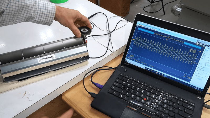
Anything that rotates can quickly spin itself into shrapnel if it’s not properly balanced, and the DIY power tools in [Matthias Wandel]’s shop are no exception. Recent upgrades to his jointer have left the tool a bit noisy, so he’s exploring machine vibrations with this simple but clever setup. Using nothing but a cheap loudspeaker and an oscilloscope, [Matthias] was able to characterize vibrations in a small squirrel-cage blower — he wisely chose to start small to validate his method before diving into the potentially dangerous jointer. There was quite a lot to be learned from the complex waveforms coming back from the transducer, analysis of which was greatly helped by the scope’s spectrum analyzer function. The video below shows the process of probing various parts of the blower, differentiating spectral peaks due to electrical noise rather than vibration, and actually using the setup to dynamically balance the fan.
We’d rate this as yet another handy shop tip from [Matthias], and we’ll be looking out for the analysis of his jointer. Want to do the same but you don’t have an oscilloscope? No problem — an earbud and Audacity might be all you need.


I’ve found that any piezo speaker makes a killer mechanical transducer, especially since even small signals can product 3Vp-p!
That’s a really neat idea to me so, I’ve been tinkering with it for a couple days. I don’t know much on the mechanical end of things, but I’m wondering if like a denounce capacitor or maybe some kinda passive filter would be helpful if one was measuring a specific range. Do you that might be helpful or just a bit superfluous?
Thanks for the inspiration. I love Hackaday for coming up with the “why didn’t I think of that?” moments :-)
If you want to reduce the impact of magnetic induction, you can make an optical pickup (i.e. using a slotted optocoupler from an old printer).
Analog accelerometers are also great and you get the output in calibrated units. E.g. ADXL335 breakout boards are cheap.
Great report on a great practical experiment. Thanks!!
For bonus points do what the pros do, and have been doing for decades: Put an optical pickup on the shaft to generate a once-per-rev trigger to the recorder, and measure a pickup on each end of the shaft simultaneously.
Measure amplitude and phase of each pickup with respect to the start pulse.
Put a test mass on for calibration, run the arithmetic, and (in principle) get the solution in a single iteration.
If you can’t be bothered to look up how it’s been done before, or don’t want to do the arithmetic, then enjoy the iteration.
I see this as the bonus points method myself, something that needs very little in the way of tools or setup and will get to towards a good result very cheaply, and in real world conditions.
Sometimes simpler tools that require a tiny bit more human effort are still better, sometimes its in greater final precision as the human checks their work as they go along more times rather than the fancy box of tricks does the initial measurement, did the maths and assumed their measurements and the calculated corrections are perfectly executed, and sometimes its just because seeing it for yourself gives you a feel for the problems you are troubleshooting, and a chance to notice the oddity in a related system that is part of the problem.
Not saying your preferred method is wrong, as its certainly good and should be quicker, but if you can’t actually understand the way it all works, get the readings and calculate your results yourself (at least in theory) its putting a great deal of trust into your rig to work its magic with no comprehension as to why, or what the odd result might mean, if you even notice the result is odd – like the car diagnostic ports, great at telling you what the car thinks is wrong, but frequently it will only be part of the problem, if its actually part of the problem at all rather than just a symptom.
Uh, that’s my point. If you DO understand how it works, you can measure the phase and amplitude and predict exactly how much and where to place the balance mass. None of the iterating cut-and-try caveman approach required. No special tools required either.
Isn’t much of the point of hacking to *learn* how something works?
Indeed but usually your ‘pro’ tools do it all for you, or at least instruct you to replace/place x at y, if you don’t look at the data yourself, or wouldn’t really know what it means as you haven’t played with it, the most sophisticated and efficient computer/calculator assisted methods are failure prone, because the operator just has to trust the machine output, they literally can do nothing else, as they don’t understand it, and they won’t spot that odd result that points to perhaps the motor pulley being very out of round, etc.
Sure, there are all-in one ‘pro’ tools to accelerate the process. Tire balancing machines are one example.
But I wasn’t saying to use an off-the shelf appliance to do this (though they exist and are cheap).
I say you could just add the phase information and do this much more quickly if you’re willing to understand the problem and do a bit of arithmetic.
No extra ‘pro’ tools required, and it’s the exact opposite of trusting a machine to do it: you *have* to understand what you’re doing. Otherwise you’re faffing around, doing the cut-and-try neanderthal approach that kinda-sorta works much of the time.
Yet another excellent video from Matthias.
I saw he used: “multi viranalyzer”, which is apparently software for the “Instrustar” USB scopes.
Also, when balancing, you have two variables for the weight, location and mass, and I wonder if balancing would be easier if combined with an rpm sensor to determine the phase shift.
The results from his modified speaker also look quite good. It is also modeled after a “contact microphone”
balancing would be easier if combined with an rpm sensor to determine the phase shift.
Yes, much, much easier. You can do it in a single iteration, if there are not too many confounding issues (like flexible shafts or supports).
Doing it the Matthias Way(TM) will get the job done but, like so much of his work, seems like an exercise in self-flagellation. It might be righteous and fulfilling to go through the pain, but there are better ways.
I described a similar technique in my book Marvelous Magnetic Machines.
https://www.artisanideas.com/product/9781733325042/Marvelous-Magnetic-Machines-Building-Model-Electric-Motors-from-Scrap.html?cid=
I used a laptop computer, Audacity, a piezo transducer to measure displacement due to vibration, and an opto-coupler/sensor to generate a once-per-rev clock. The Piezo transducer feeds one channel, the clock feeds the other. Using the the two waveforms, it’s possible to determine not only the relative weight needed to correct balance, but where to place it.
Some low pass filtering is in order, and when balancing passive parts (a flywheel or rotor, for example) one must decouple and render orthoganal any vibration generated by the driver. There are sevetal ways to do this, which I describe.
The problem you have described is synchronous demodulation and segmentation. The error signal you would get is the same frequency as the rpm of the motor, and you then just need to determine its phase. The segmentation comes from you not being able to place corrections just anywhere, only on blades (segments).
What you did is exactly what the big, expensive balancer machines do at a greater cost than your set-up. Scopes included.
Good Job.
“Aaaaaand now for my next trick, I am going to balance an oscilloscope on a motor!”
You can also use the one from http://www.dynexhobby.com