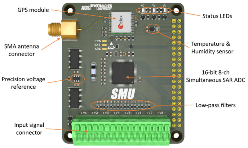
A team from the Institute for Automation of Complex Power System (ACS) at RWTH Aachen University have been working for a while on the analysis of widely distributed power systems. In a drive to move away from highly specialised (and expensive) electronics platforms, they have produced some instrumentation designed to operate with the Raspberry Pi platform, and an open source software stack. They call the platform the SMU (Synchronised Measurement Unit.) The SMU consists of a HAT sitting on an RPi3, inside a 3D printed box that is intended to attach to a DIN rail. After all, this is supposed to be an industrial platform.
Hardware wise, the star of the show is the Texas Instruments ADS8588S which is a 16-bit 8-channel simultaneous sampling ADC. This is quite a nice device, with 200 kSPS throughput and a per-channel programmable front end, packaged in a hacker-friendly 64-pin QFP. What makes this project interesting however, is how they solved the problem of controlling the sampled data acquisition and synchronisation.
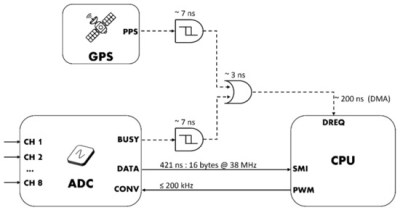
By programming the ADC into byte-parallel mode, then using the BCM2837 Secondary Memory Interface (SMI) block together with the DMA, samples are transferred into memory with minimal CPU overhead. An onboard U-Blox Max-M8 GNSS module provides a 1PPS (top of second pulse) signal, which is combined with the ADC busy signal in a very simple manner, enabling both sample rate control as well as synchronisation between multiple units spread out in an installation. They reckon they can get synchronisation to within 180 ns of top-of-second, which for measuring relatively slow-changing power systems, should be enough. The HAT PCB was created in KiCAD and can be found in the SMU GitHub hardware section, making it easy to modify to your needs, or at least adjust the design to match the parts you can actually get your hands on.
Software-wise, the full stack is provided from the kernel module that deals with the low-level stuff, offering up /dev/SMU, right up to the management daemon and a QT-based GUI. A full system level description can be found on the associated Open Access article.
We see many power monitor projects on Hackaday, since a little more knowledge of power usage can save you in the long run. Here’s another RPi HAT project, for just this purpose. Of course, you don’t have to be this clever, if you have an appropriate electricity meter, you could just count blinks and call it a day.


“They call the platform the SMU (Synchronised Measurement Unit.)”
So these measurement “experts” don’t know that name and acronym is confusing? It is in direct conflict with SMU – Source Measure Unit.[1][2] A real SMU instrument can source and sink power in all four quadrants. That is not what their SMU thing does at all. Real SMUs are usually under NTP time-synchronized computer control via a serial, IEE-488/HPIB/GPIB [3], or PXI [4] bus so all measurements are time stamped and reasonably coherent to begin with. But yes, real SMUs are complex to build, hence expensive. So their “SMU” probably does have a niche in the market, just don’t call it an SMU – because it isn’t.
1. Source Measure Unit
https://en.wikipedia.org/wiki/Source_measure_unit
2. Source Measure Units – Keysight
https://www.keysight.com/us/en/products/source-measure-units-smu.html
3. IEE-488
https://en.wikipedia.org/wiki/IEEE-488
4. PXI (PCI eXtensions for Instrumentation)
https://en.wikipedia.org/wiki/PCI_eXtensions_for_Instrumentation
I know right? That was my first thought. “Oh goody another SMU design to dig into!” followed by “Oh, not a source-measure unit then. Boo.”
Still, it might be useful to someone, but a different name would have been better,
Beside the application of the device, primarily intended to be used in power systems, the device itself is an open source high performance DAQ on Raspberry Pi. Maybe there are more than 1-2 people out there interested in how to implement a synchronous high-speed multichannel DAQ in an OS environment..
I for one would like to use it. Wouldn’t mind hooking it up to my 3 phase system to do some albeit useless measurements that I used to do in uni. And could give me some insight into the grid stability. Phasor diagrams ect..
I agree, the acronym might be confusing, but the purpose of the device has nothing in common with a Source Measurement Unit. If you read the article attached to the article before giving public display of your knowledge, than you would have understood that it is a generalization of the concept of PMU – Phasor Measurement Unit and DMU – DC Measurement Unit, device used to monitor in real time the power distribution grid. As these devices have to be distributed in the field, the main way of doing it is by synchronizing the time base to a GPS signal.. I challenge you to install thousands of Source Measurement Unit in the field…
My thoughts exactly. Acronym collision can be a pain, but it’s no reason for someone to throw a hissy fit.
Having working before in substations, the price of equipment that essential does when this does (not talking about the protection equipment that reads the same signal but causes the breakers to open) is silly expensive.
Southern Methodist University?
B^)
Seriously, I am at the moment very much fed up with electronics. I have been trying to find a multi-channel parallel ADC for weeks. I mean: one that is available. One that I can buy now and possibly in a year’s time, too.
No luck. And that goes for the ADS8588S, too.
Lead time between 50 and 70 weeks. And guess where in the queue my 5 pieces will be placed.
No. I have been focusing on software more and more, recently.
Electronics as a hobby is broken beyond repair.
You want to try making a living (or at least partially) out of electronics prototyping! Don’t. I’m redesigning stuff over and over based on supply, and months behind schedule in some cases. It’s just so depressing.
I feel with you. Have a friend who’s in the business and he told me about a supplier who has increased the price for a data aquisition IC by a factor of 70 or 80. FACTOR 80, not by 80%.
Reason: Well, you have some long-term service contracts, haven’t you? And I have the ICs.
These people know exactly how difficult it is to re-design a whole new analogue front-end and thrive on it.
Meh!
Yes please don’t make a living out of electronics prototyping. Having less competition is good for me.
My approach would be to use:
a 10-bit to 15-bit ADC with a Parallel Data Bus output;
a 16-bit buffer/driver with 3-state outputs (I’d probably pick a 74G series chip that can operate above a gigahertz to maximise resolution e.g PO74G16241A) or if I needed more than 15-bit ADC a 32-bit buffer/driver (e.g. IDT74ALVCH32244);
and a cheap enough GPS chip with a reasonable precision PPS output.
Then one pin into the buffer/driver (most signifiant or least signifiant bit) I’d feed the GPS 1 PPS.
There would be reasonably constant delay between that bit being pulsed and the corresponding sample arriving, but that would be need to be compensated in software after calibration. But since every ~30 centimeters (~11.8″) of coaxial cable will add about 1 ns of delay some compensation values would always be needed anyhow.
But I would be looking from a SDR (Software Defined Radio) perspective, synchronising many distributed devices (Clocked via a VC-TCXO, calibrated once, and initialised using that value with a SPI 12bit DAC by a MCU).
As for “open source” – On the docs page, it stated:” NO LICENSE. ALL RIGHTS RESERVED.” Huh?
Thanks for reporting this, the docs section was a new repository still not filled. This is now fixed
What a great project, What are the models of Ct’s and Pt’s used in the project that you connected for voltage and current measurment?