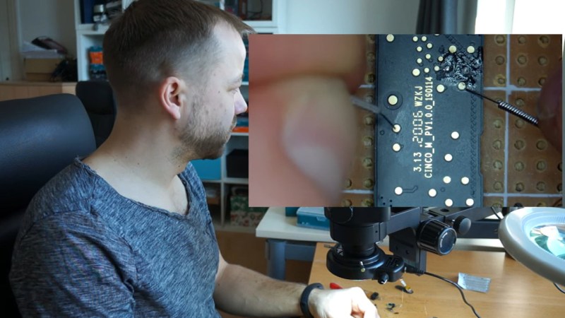
Say you’re tinkering with a smart device powered by a CPU that uses Serial Wire Debug (SWD), but doesn’t mark the testpoints. Finding SWD on a board — how hard could it be? With [Aaron Christophel]’s method, you can find the SWD interface on a PCB within a few minutes’ time. All you need is two needles, a known-to-be-ground connection, an SWD dongle of some kind, and a computer with an audio output. What’s best — you could easily transfer the gist of this method to other programming interface types!
The idea is simple: you wire the ground up, connect the needles to SWDIO and SWCLK, launch [Aaron]’s Python script, then start poking around all the unnamed test points. The script runs JLink software to probe for SWD devices attached to the probes — if an SWD interface isn’t found, it beeps idly, but as soon as the device is detected, your computer will start beeping at you in a lively manner. In this way, you don’t have to re-scan devices manually, solder to any test points except the GND one, or try and hold both probes on test points with one hand – the scanning process itself is hands-free.
Depending on how many points your board has and whether you try to optimize the process by probing points closest to the SWD pins on the CPU, you might hit the jackpot immediately, or you might have to poke around for a minute-two. That said, [Aaron]’s method seems to be the best you can do while remaining relatively extra-hardware-free, and if you want to make it a tinge more permanent, clothespins are there for you.
In case you don’t mind extra hardware – could we interest you in some 3D printed needle probe desks? There’s a wide variety of those, whether you’d like some tentacle-like ones, or ones that make your desk look like like an acupuncture table. Or, say, would you like a more automatic method of finding all kinds of debug interfaces? Then JTAGulator might be what you’re looking for.


>you could easily transfer the gist of this method to other programming interface types!
Only if you have more than 2 hands… The idea of accustic feedback is still a good one.
well, if you’ve been soldering for a decent amount of time, you’re probably already used to needing more than 2 hands, and skill-wise might’ve gotten to the point where one could say you effectively have grown an extra hand or two ;-P holding two or three probes per hand sounds pretty realistic to me. Plus, SWD, UART and I2C all need two pins, and with those, you basically cover majority of the ground you could need; it’s JTAG that stands out, and the amount of combinations alone will have you reach for a JTAGulator.
Fair point. I was thinking JTAG, but indeed, with so many combinations you don’t wan’t to manually test everything. The problem with JTAGulator and stuff like this is that you still need to solder potentially a lot of (really fine) wires to (really small) testpoints. I was wondering if there is some company selling IDC-connectors with let’s say 30cm of fine cable attached and *pre-tinned ends* to make work like this faster/less painful. You can certainly get this as a custom made cable, but i wonder if you can find it for reasonably small money somewhere.
Great idea. At first I was thinking he would use an audio amplifier and listen to the handshake signal analog style, but that might not work.
I love the idea, thinking of ways of combining the abilities of the computer/microcontroller and the human interface. For example, if you have two pins, and a configurable debug probe where you can swap the SWDIO and SWCLK pins in software, you could play one sound when testing one configuration, then reverse the pins and play a different sound when that fails. So as a human, just listen for two beeps per pair of pins to determine whether it is successful or not, as opposed to physically swapping the needles from one pad to another.
I’m thinking something like the Glasgow would be ideal for this, with the FPGA making it trivial to change the pin configuration, but perhaps the Black Magic Probe or hosted BMPA with an FTDI 2232 might also work?
Or any other SOC like an ESP32 :)
https://youtu.be/Iu6RoXRZxOk
What are you even doing with all those fitness trackers? I still have a few DS-D8 from eons ago and only found a use-case for one of them…
I like the idea of trying both pin combinations. Have it default to that mode and then allow a key press like pressing the Spacebar to toggle back and forth between this new mode and the old mode. That way it would be a bit easier to first detect which 2 pins were for the SWD port. Press the key to switch modes and then you would need to perform a maximum of 1 test lead swap to learn which of the 2 pins was SWCLK and which was SWDIO.
For the lazy ones, here is the script he is using.
source: The Youtube Video Description @ https://www.youtube.com/watch?v=r6hGHZEtEE0
import subprocess
import winsound
def check_connection():
output = subprocess.check_output(“JLink.exe -device DA14697 -NoGui 1 -CommandFile jlink_auto_file.jlink”, shell=True).decode()
if “Cannot connect to target” in output:
print(“Not found!”)
winsound.Beep(500, 100)
else:
print(“Found!”)
winsound.Beep(4000, 100)
winsound.Beep(1000, 100)
winsound.Beep(4000, 100)
winsound.Beep(1000, 100)
winsound.Beep(4000, 100)
winsound.Beep(1000, 100)
winsound.Beep(4000, 100)
winsound.Beep(1000, 100)
while 1==1:
check_connection()
————————
jlink scriptfile:
jlink_auto_file.jlink:
decvice DA14697
if SWD
speed 40000
connect
exit