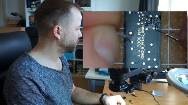
The hack's author performing the operation described at his workdesk, with a separate camera window showing the acupuncture needles being used to touch the board points

Find SWD Points Quickly, No Extra Hardware Needed

Say you’re tinkering with a smart device powered by a CPU that uses Serial Wire Debug (SWD), but doesn’t mark the testpoints. Finding SWD on a board — how hard could it be? With [Aaron Christophel]’s method, you can find the SWD interface on a PCB within a few minutes’ time. All you need is two needles, a known-to-be-ground connection, an SWD dongle of some kind, and a computer with an audio output. What’s best — you could easily transfer the gist of this method to other programming interface types!

The idea is simple: you wire the ground up, connect the needles to SWDIO and SWCLK, launch [Aaron]’s Python script, then start poking around all the unnamed test points. The script runs JLink software to probe for SWD devices attached to the probes — if an SWD interface isn’t found, it beeps idly, but as soon as the device is detected, your computer will start beeping at you in a lively manner. In this way, you don’t have to re-scan devices manually, solder to any test points except the GND one, or try and hold both probes on test points with one hand – the scanning process itself is hands-free.

Depending on how many points your board has and whether you try to optimize the process by probing points closest to the SWD pins on the CPU, you might hit the jackpot immediately, or you might have to poke around for a minute-two. That said, [Aaron]’s method seems to be the best you can do while remaining relatively extra-hardware-free, and if you want to make it a tinge more permanent, clothespins are there for you.

In case you don’t mind extra hardware – could we interest you in some 3D printed needle probe desks? There’s a wide variety of those, whether you’d like some tentacle-like ones, or ones that make your desk look like like an acupuncture table. Or, say, would you like a more automatic method of finding all kinds of debug interfaces? Then JTAGulator might be what you’re looking for.

Continue reading “Find SWD Points Quickly, No Extra Hardware Needed”

Unbricking A SEGGER J-Link V9 Debug Probe

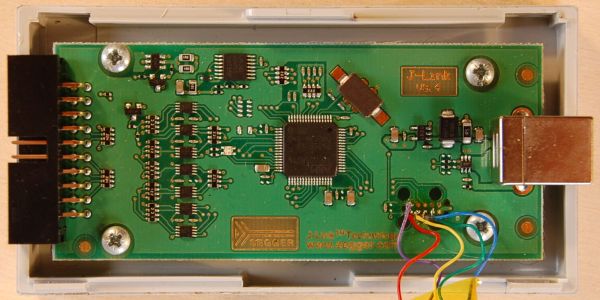
Last year [Emil] found themselves in the situation where a SEGGER J-link debug probe suddenly just stopped working. This was awkward not only because in-circuit debuggers are vital pieces of equipment in embedded firmware development, but also because they’re not that cheap. This led [Emil] to take the device apart to figure out what was wrong with it.

After checking voltages on the PCB, nothing obvious seemed wrong. The Tag-Connect style JTAG header on the PCB appeared to be a good second stop, requiring only a bit of work to reverse-engineer the exact pinout and hook up an ST-Link V2 in-circuit debugger to talk with the STM32F205RC MCU on the PCB. This led to the interesting discovery that apparently the MCU’s Flash ROM had seemingly lost the firmware data.

Fortunately [Emil] was able to flash back a version of the firmware which was available on the internet, allowing the J-Link device to work again. This was not the end of the story, however, as after this the SEGGER software was unable to update the firmware on the device, due to a missing bootloader that was not part of the firmware image.

Digging further into this, [Emil] found out a whole host of fascinating details about not only these SEGGER J-Link devices, but also the many clones that are out there, as well as the interesting ways that SEGGER makes people buy new versions of their debug probes.

(Thanks Zelea for the tip)

Adding A Debugger To A Teensy 3.5/3.6

The Teensy is a powerful ARM-based development board with loads of features that can do fun stuff with USB as well. Like many dev boards, it uses a less powerful processor as an interface. Teensy designer [Paul Stoffregen] added a debug header to allow direct SWD JTAG access to the main chip, but the interface microcontroller has to be silenced for that to work, and the code to do so is still in progress.

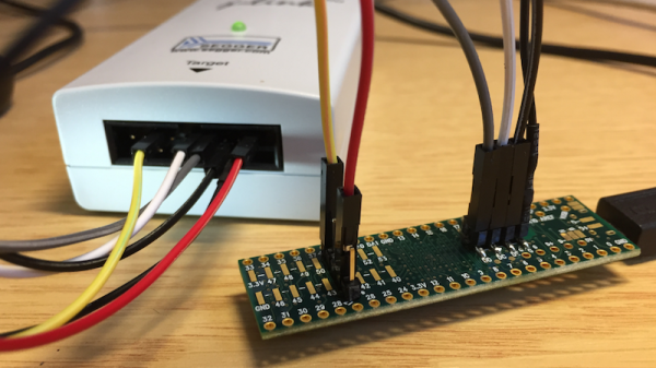
Impatient, [Erich Styger] documents the changes he made to add support for the J-Link SWD protocol by removing the offending NXP Kinetis KL02Z that serves as the as the onboard interface and bootloader that helps the Arduino IDE talk to the K64F which is the main chip. After the KL02Z was removed, [Erich] populated the debug headers and then wired up the Segger J-Link to the board and tested it out with Eclipse, GDB, and standard SWD debug tools.

The end result is a Cortex M4F board that can work with standard tools at a third of the price of the Kinetis’ development board. [Paul Stoffregen] confirms that the debugging functionality will be added to the bootloader code soon but until then, a hardware hack is a working, if brutal, approach to debugging on the platform.

More information on the JTAG interface is available for the interested. And if Teensy isn’t your thing, you might consider an STM32-based development board.