Testing The Raspberry Pi Debug Probe

We mentioned the Raspberry Pi Debug Probe when it was launched, a little RP2040-based board that provides both a USB-to-UART and an ARM SWD debug interface. [Jeff Geerling] was lucky enough to snag one, and he’s put it through its paces in a handy blog post.

The first question he poses is: why buy the Pi offering when cheaper boards can be found on AliExpress and the like? It’s easily answered by pointing to the ease of setting up, good documentation and support, as well as the device’s reasonable price compared to other commercial probes. It also answered a personal question here as he hooked it up to a Pico, why it has three jumpers and not the more usual multi-way header we’ve seen on other ARM platforms. We should have looked at a Pico more closely of course, because it matched neatly to the Pi product. On the Pico they’re at the edge, while on the Pico W they’re in the center.

No doubt if the latest addition to the Pi stable has any further revelations we’ll bring them to you. But it’s worth a quick look at this piece to see a real experience with their latest. Meanwhile, take a quick look at our launch coverage.

New Product: The Raspberry Pi Debug Probe

It’s fair to say that among the new product launches we see all the time, anything new from the folks at Raspberry Pi claims our attention. It’s not that their signature Linux single-board computers (SBCs) are necessarily the best or the fastest hardware on paper, but that they’re the ones with meaningful decade-plus support. Add to that their RP2040 microcontroller and its associated Pico boards, and they’re the one to watch.

Today we’ve got news of a new Pi, not a general purpose computer, but useful nevertheless. The Raspberry Pi Debug Probe is a small RP2040-based board that provides a SWD interface for debugging any ARM microcontroller as well as a more generic USB to UART interface.

The article sums up nicely what this board does — it’s for bare metal ARM coders, and it uses ARM’s built-in debugging infrastructure. It’s something that away from Hackaday we’ve seen friends using the 2040 for as one of the few readily available chips in the shortage, and it’s thus extremely convenient to have readily available as a product.

So if you’re a high level programmer it’s not essential, but if you’re really getting down to the nuts-and-bolts of an ARM microcontroller then you’ll want one of these. Of course, it’s by no means the first SWD interface we’ve seen, here’s one using an ESP32.

The hack's author performing the operation described at his workdesk, with a separate camera window showing the acupuncture needles being used to touch the board points

Find SWD Points Quickly, No Extra Hardware Needed

Say you’re tinkering with a smart device powered by a CPU that uses Serial Wire Debug (SWD), but doesn’t mark the testpoints. Finding SWD on a board — how hard could it be? With [Aaron Christophel]’s method, you can find the SWD interface on a PCB within a few minutes’ time. All you need is two needles, a known-to-be-ground connection, an SWD dongle of some kind, and a computer with an audio output. What’s best — you could easily transfer the gist of this method to other programming interface types!

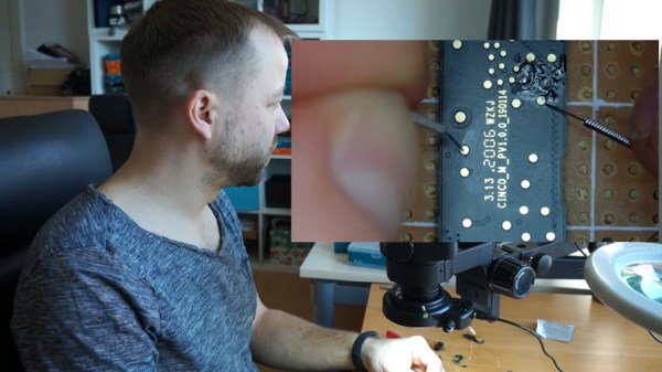
The idea is simple: you wire the ground up, connect the needles to SWDIO and SWCLK, launch [Aaron]’s Python script, then start poking around all the unnamed test points. The script runs JLink software to probe for SWD devices attached to the probes — if an SWD interface isn’t found, it beeps idly, but as soon as the device is detected, your computer will start beeping at you in a lively manner. In this way, you don’t have to re-scan devices manually, solder to any test points except the GND one, or try and hold both probes on test points with one hand – the scanning process itself is hands-free.

Depending on how many points your board has and whether you try to optimize the process by probing points closest to the SWD pins on the CPU, you might hit the jackpot immediately, or you might have to poke around for a minute-two. That said, [Aaron]’s method seems to be the best you can do while remaining relatively extra-hardware-free, and if you want to make it a tinge more permanent, clothespins are there for you.

In case you don’t mind extra hardware – could we interest you in some 3D printed needle probe desks? There’s a wide variety of those, whether you’d like some tentacle-like ones, or ones that make your desk look like like an acupuncture table. Or, say, would you like a more automatic method of finding all kinds of debug interfaces? Then JTAGulator might be what you’re looking for.

Continue reading “Find SWD Points Quickly, No Extra Hardware Needed”

The microcontroller described in the article, on the PCB taken out of the kettle

Dumping Encrypted-At-Rest Firmware Of Xiaomi Smart Kettle

[aleaksah] got himself a Mi Smart Kettle Pro, a kettle with Bluetooth connectivity, and a smartphone app to go with it. Despite all the smarts, it couldn’t be turned on remotely. Energized with his vision of an ideal smart home where he can turn the kettle on in the morning right as he wakes up, he set out to right this injustice. (Russian, translated) First, he tore the kettle down, intending to dump the firmware, modify it, and flash it back. Sounds simple enough — where’s the catch?

This kettle is built around the QN9022 controller, from the fairly open QN902X family of chips. QN9022 requires an external SPI flash chip for code, as opposed to its siblings QN9020 and QN9021 which have internal flash akin to ESP8285. You’d think dumping the firmware would just be a matter of reading that flash, but the firmware is encrypted at rest, with a key unique to each MCU and stored internally. As microcontroller reads the flash chip contents, they’re decrypted transparently before being executed. So, some other way had to be found, involving the MCU itself as the only entity with access to the decryption key.

Continue reading “Dumping Encrypted-At-Rest Firmware Of Xiaomi Smart Kettle”

ESP32 Turned Handy SWD Flasher For NRF52 Chips

Got an nRF52 or nRF51 device you need to flash? Got an ESP32 laying around collecting dust? If so, then firmware hacking extraordinaire [Aaron Christophel] has the open source code you need. His new project allows the affordable WiFi-enabled microcontroller to read and write to the internal flash of Nordic nRF52 series chips via their SWD interface. As long as you’ve got some jumper wires and a web browser, you’re good to go.

In the first video below [Aaron] demonstrates the technique with the PineTime smartwatch, but the process will be more or less the same regardless of what your target device is. Just connect the CLK and DIO lines to pins GPIO 21 and GPIO 19 of the ESP32, point your web browser to its address on the local network, and you’ll be presented with a straightforward user interface for reading and writing the chip’s flash.

As demonstrated in the second video, with a few more wires and a MOSFET, the ESP32 firmware is also able to perform a power glitch exploit on the chip that will allow you to read the contents of its flash even if the APPROTECT feature has been enabled. [Aaron] isn’t taking any credit for this technique though, pointing instead to the research performed by [LimitedResults] to explain the nuts and bolts of the attack.

We’re always excited when a message from [Aaron] hits the inbox, since more often that not it means another device has received an open source firmware replacement. From his earlier work with cheap fitness trackers to his wildly successful Bluetooth environmental sensor hacking, we don’t think this guy has ever seen a stock firmware that he didn’t want to immediately send to /dev/null.

Continue reading “ESP32 Turned Handy SWD Flasher For NRF52 Chips”

JTAG Hat Turns Raspberry Pi Into A Networked Debugger

Over the last year or so we’ve noticed a definite uptick in the number of folks using OpenOCD on the Raspberry Pi. It’s a cheap and convenient solution for poking around with various microcontrollers and embedded devices, but not always the most elegant. Looking to improve on the situation somewhat, [Matthew Mets] has been working on a purpose-built JTAG Hat to clean things up a bit.

Onboard level shifters allow you connect to JTAG and SWD interfaces from 1.8 to 5 V, and if you power the target device from the Pi itself, there’s even support for measuring the voltage and current. To connect up to your target, the open hardware board features a “legacy” pin header perfect for jumper wires, as well as a dedicated 10-pin Cortex Debug Connector. Whether you spin up your own or buy one assembled, it certainly looks like a tool worth having around if you often find yourself working with the appropriate chips.

In addition to the design files for the hardware, [Matthew] has also provided some nice documentation on how to get the software side of things up and running. Starting with a blank SD card, it walks you through the initial setup of the Raspberry Pi all the way through the installation and configuration of a patched version of OpenOCD designed to support the JTAG Hat.

If you spend more time working with 8-bit AVR chips, don’t worry. Last year we covered a similar project to turn everyone’s favorite Linux SBC into an all-in-one microcontroller development powerhouse.

Exploring The New Super Mario Game & Watch

Nintendo has revived the classic Game & Watch, this time in glorious full-color and running the same Super Mario Bros that first graced the Nintendo Entertainment System (NES) back in 1985. Even though it’s only been on the market for a few days, [stacksmashing] has already made some impressive progress towards unlocking the full potential of this $50 retro handheld.

It will come as no surprise to the average Hackaday reader that what we’re looking at here is a pocket-sized NES emulator, but until [stacksmashing] cracked his open, nobody was quite sure what kind of hardware is was running on. Thankfully there wasn’t an epoxy blob in sight, and all of the chips were easily identifiable. Armed with the knowledge that the Game & Watch is running on a STM32H7B0 microcontroller with a nearby SPI flash chip holding the firmware, it was just a matter of figuring out how the software worked.

Connecting to the SWD header.

It didn’t take long to find that an unpopulated header on the board would give him access to the Serial Wire Debug (SWD) interface of the STM32, though unfortunately he found that the chip’s security mode was enabled and he couldn’t dump the firmware.

But he was able to dump the RAM through SWD, which allowed him to identify where the Super Mario Bros NES ROM lived. By connecting the SPI flash chip to a reader and comparing its contents with what the system had in RAM, [stacksmashing] was able to figure out the XOR encryption scheme and come up with a tool that will allow you to insert a modified ROM into an image that can be successfully flashed to the chip.

So does that mean you can put whatever NES ROM you want on the new Game & Watch? Unfortunately, we’re not quite there yet. The emulator running on the device has a few odd quirks, and it will take some additional coaxing before its ready to run Contra. But we’ve seen enough of these devices get hacked to know that it’s just a matter of time.

Continue reading “Exploring The New Super Mario Game & Watch”