
Last time, I’ve shared my experience on why you might want to consider a laptop motherboard for a project of yours, and noted some things you might want to keep in mind if buying one for a project. Now, let’s go through the practical considerations!
Making It Boot
Usually, when you plug some RAM and a charger into a board, then press the power button, your board should boot up and eventually show the BIOS on the screen. However, there will be some caveats – it’s very firmware-dependent. Let me walk you through some confusing situations you might encounter.
If the board was unpowered for a while, first boot might take longer – or it might power on immediately after a charger has been plugged in, and then, possibly, power off. A bit of erratic behaviour is okay, since boards might need to do memory training, or recover after having lost some CMOS settings. Speaking of those, some boards will not boot without a CMOS battery attached, and some will go through the usual ‘settings lost’ sequence. Sometimes, the battery will be on a daughterboard, other times, especially with new boards, there will be no CR2032 in sight and the board will rely on the main battery to provide CMOS settings saving functions – in such case, if you don’t use the battery, expect the first boot to take longer, at least. Overall, however, pressing the power switch will cause the board to boot.
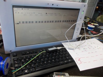
Don’t have a LCD to go with your mainboard? Some boards will not show any image through HDMI or VGA ports during boot, only programmed to use the internal screen. Other boards will show an image through VGA, but not HDMI, or vice-versa. If you stumble upon such a board, do know that it will show an external image when you boot into the OS – either at the bootloader stage or at the OS bootscreen stage. If you’d like to check whether your board is booting, connect an external keyboard to it – as you will likely want to do anyway. During boot, the three LEDs on your keyboard (NumLock, CapsLock and ScrollLock) will flash – you’ve likely seen this on-boot pattern, and this situation is no different. In addition to that, if they don’t flash, you can check whether your CPU is responsive, by pressing the CapsLock key and seeing if the associated LED toggles.
 Let’s say you have a live CD or OS install flashdrive. Are you plugging your boot flashdrive into a USB3 port on your board? Try a USB2-only port – many boards, especially early USB3 boards with PCIe controllers, won’t support booting over USB3. Whether you’re using a flashdrive or a HDD with an already installed OS, if it doesn’t boot into that, you should check – is BIOS set for UEFI or legacy boot mode? It’s not always both, and sometimes USB boot is disabled by default. If you’re booting blind, without BIOS access, images like SystemRescueCD are programmed with support for both UEFI and legacy modes, so you might want to put that onto a LiveUSB to check.
Overall, I’ve had great success booting laptop boards – as much as the initial behaviour can be confusing, now you know what to expect. The power button often could use being extended – I usually solder to the power button pins and add a cable, which helps the unideal mechanics of the default power button location. You can put some glue on the solder points afterwards, and make sure to add some strain relief to the cable to avoid the cable breaking off eventually. Try pulling it through one of the multiple holes that all motherboards have.
Mechanicals
Let’s talk more about the mechanical aspects! Laptop boards don’t have any kind of standardized mounting hole patterns, and measuring out the hole locations might just be a waste of your time. The simplest way you can go is mounting it to a wood board or sheet of some kind – I use lasercuttable birch sheets a lot for quick “put a board somewhere” builds.
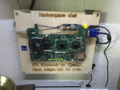 Place the motherboard on top of the sheet, hold it steady, use a pencil or marker to mark the hole locations, move the board away, drill through the marked holes, then use something to fasten the board – standoffs will work wonders, and even self-tapping screws or nails will work in a pinch if they’re long and thin enough for the motherboard holes. Make sure that the mainboard isn’t bent after you’ve fastened it to the sheet! If you need to add speakers, battery, WiFi antennas, USB hubs, feel free to fasten them to the same sheet – given a drill, some glue and tape, you can do it all.
That said, you don’t have to go for quick and dirty; laptop motherboard reuse can also look good. If it’s visible, feel free to mount a piece of lasercut acrylic in front of it, both for protection and for fancy looks purposes. Or, perhaps, tech it up – route the wires in a pretty way, add some functional or aesthetic LEDs, use cables and connectors of the same colour as the PCB, there’s plenty of ways to go about it. Alternatively, you can omit all of it and stove the board away under a work desk – if it’s part of your infrastructure, it’s not meant to be touched often, anyway.
One thing, however – make sure you protect the board from any metal parts that might short it out. I’ve built a pretty fun project once – an AiO with a lasercut layered case, built basically out of leftovers, and I aimed it to be a luggable machine for hackerspace use. Sadly, as I was building it, I put some metal parts onto it without disconnecting the power – and the mainboard perished. Ultimately, the project wasn’t worth to me enough that I would pay 50 € for a new board, and I had to shelve it – such occasions are sad, and entirely preventable as long as you’re cautious.
Want More? There Is More
Of course, you might not be completely satisfied by what an off-the-shelf mainboard has in store.
Could you benefit from some I2C in your project, whether for sensors, drivers or something else? Laptop motherboards have plenty of I2C, and loading the i2c-dev kernel module on Linux will show you quite a few. You can find I2C on HDMI and VGA ports, slots like ExpressCard, as well as onboard sensor ICs and RAM slots – though the two latter ones might not be user-accessible. You won’t get GPIOs, unless you manage to reprogram your EC – however, you can absolutely connect a GPIO expander chip over I2C, like the PCF8574 or the MCP23017, and control whatever low-tech device you want. On Windows, I2C isn’t accessible save for hacky or expensive solutions, so you might want to go the external microcontroller route instead if Windows is a requirement.
Whichever signals you might want to solder to, they’re usually well-documented or can easily be figured out. I2C on HDMI, VGA, and ExpressCard is extensively documented. USB can be figured out from differential pair trace layout and things like signal inductor pairs, and for power buttons, there’s no shortage of pins to solder to. However, if you’re looking for more, schematics will help, and here’s how.
Say, you want to add a few buttons to your project – you could absolutely use the keyboard connector, because many laptop keyboards are straightforward key matrices, not even requiring any diodes in a way that the usual keyboards do. However, you will want to know which pins on the keyboard connector are rows and which are columns, so that you know where buttons could be wired up to. Schematics will tell you that, and way more. If your specific board doesn’t have schematics available, you can at least check for keyboard compatibility on online marketplaces, and see if any of the claimed-compatible laptops has schematics available – if a laptop keyboard is compatible with a few different laptops, knowing the pinout for one will be enough.
 Need a bit more power in your project, and don’t mind the power source being a tad variable when on battery power? Laptops usually have a main power rail that provides power to all the other rails, from 3.3 V and 5 V to the CPU power input. It has a wide voltage range – as high as the charger voltage, or as low as the lower bound of the included battery pack. As you can guess, this rail is powered from the charger when it’s connected, and from the battery otherwise. If your board needs to power, say, an Ethernet switch that wants 9 V, adding a sufficiently beefy buck converter tapped into the main power rail will save you from needing an external power brick.
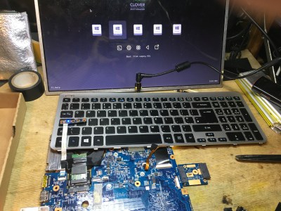
Oh, and there’s a trick the 2.5″ HDD industry doesn’t want you to know. If you have a free PCIe slot in your laptop, be it from miniPCIe or from ExpressCard, you can put a NVMe SSD into it using an adapter. This is useful if you have some cheap NVMe SSDs, as lower-capacity ones have been coming down in price recently, or if you want to avoid the fundamental unreliability of spinning rust while not settling for 2.5″ SSDs. If your BIOS doesn’t support booting from NVMe, use a flashdrive with Clover, or perhaps, put Clover onto an SD card plugged into the onboard SD reader – if your laptop can boot from that; not all laptops can, do check.
Software And Exploration
When it comes to software, I’d recommend going with Linux wherever possible, unless you don’t have any experience with it, and even then, it might be easy enough for you . Of course, when you want the computer to interface with some x86-only software, that usually implies a Windows requirement as well. Other than such scenarios, Linux will be overall more reliable for ‘machine dedicated to a certain task’ goal – on Windows, you usually have to wage battle to achieve the same things that we take for granted when working on a Raspberry Pi Linux stack.
Is this all? No, there’s way more that you can find – exploring the various boards you find, adding everything and the kitchen sink, building custom keyboards, tapping into PCIe links for your high-speed expansion needs, adding RAM slots where none was meant to be, replacing RAM and CPUs that wasn’t meant to be replaced, tinkering with expansion standards like miniPCIe and M.2, hacking your EC firmware, building a wooden enclosure around the board,


Also, if you need GPIOs, take a look at https://lab.whitequark.org/notes/2017-11-08/accessing-intel-ich-pch-gpios/.
For many Laptops you can find schematics, and I justed tested this on an old Dell Latitude notebook with ICH9 this weekend: https://rof.li/pic/ich9_gpio.jpg
Many of the USB OC lines that double as GPIOs were unused, and are routed to easily accessible resistor networks.
oh that’s awesome, right, I completely forgot about this one! schematics sure help with this one, too!
From context, this seems a little wrong : ” … If you want a free PCIe slot in your laptop, be it from miniPCIe or from ExpressCard, you can put a NVMe SSD into it using an adapter. .. “.
I believe you meant to say “If you have a free PCIe slot ” …
oh yeah, I didn’t rewrite that sentence fully while making last changes, thank you!
Feed the right voltage to your board instead of the battery:
https://hackaday.com/wp-content/uploads/2023/01/hadimg_laptopmobo_reuse_2.jpg
wait, what would that accomplish? I feel like that could confuse the board (specifically, the EC) due to lack of BMS and, subsequently, lack of I2C responses from it. I also gather that it could (theoretically!) result in a spicy situation if someone were to connect the DC input at the same time (which could happen accidentally, say, with a USB-C peripheral that also happens to be able to charge the laptop, or if using a dock that needs external power)
Now, something that was on HaD in the period between “me writing this article” and “this article getting published”, that I wish I mentioned – battery-less throttling is defo a thing to keep in mind! but, idk if that still happens when no battery is detected.
Are there any groups trying to extract reference code and UEFI drivers from commercial BIOS to graft into an open-source project? There is both the EDK2 project as well as CoreBoot. I do know that vendors have ‘secret sauce’ in their BIOSes that complicate things, but might it be possible at all to recover the modular pieces and somehow use them to build a less locked-down BIOS without having to completely reverse engineer everything? Is there a community already doing this?
How wouldn’t be possible to connect a desktop monitor using the internal laptops monitor screen wiring/connection?
For eDP it could be as simple as a passive adapter from the used embeddedDisplayPort connector to more normal DisplayPort.
Else would likely be more crapshot. Old RGB TTL panel interfaces might do VGA with some dirty resistor tricks, but that’s not guaranteed.
The wooden board with standoffs also works on regular ATX – if you don’t move the graphics card or it’s connections… ;-)
https://burningbecks.wordpress.com/2015/09/10/atx-to-particle-board/
If you have a x4 M.2 NVMe port you can add a graphics card, SAS HBA, or 10G ethernet etc.
Then as mentioned convert the WiFi to NVMe
M2 KEY A-E to M2 NVME Adapter is good gor desktop boards too.
https://m.aliexpress.us/item/3256804136917718.html