There’s a good chance that if you build something which includes the ability to top up a lithium-ion battery, it’s going to involve the incredibly common TP4056 charger IC. Now, there’s certainly nothing wrong with that. It’s a decent enough chip, and there are countless pre-made modules out there that make it extremely easy to implement. But if the chip shortage has taught us anything, it’s that alternatives are always good.
So we’d suggest bookmarking this opensource hardware Li-Ion battery charger design from [Shahar Sery]. The circuit uses the BQ24060 from Texas Instruments, which other than the support for LiFePO4 batteries, doesn’t seem to offer anything too new or exciting compared to the standard TP4056. But that’s not the point — this design is simply offered as a potential alternative to the TP4056, not necessarily an upgrade.
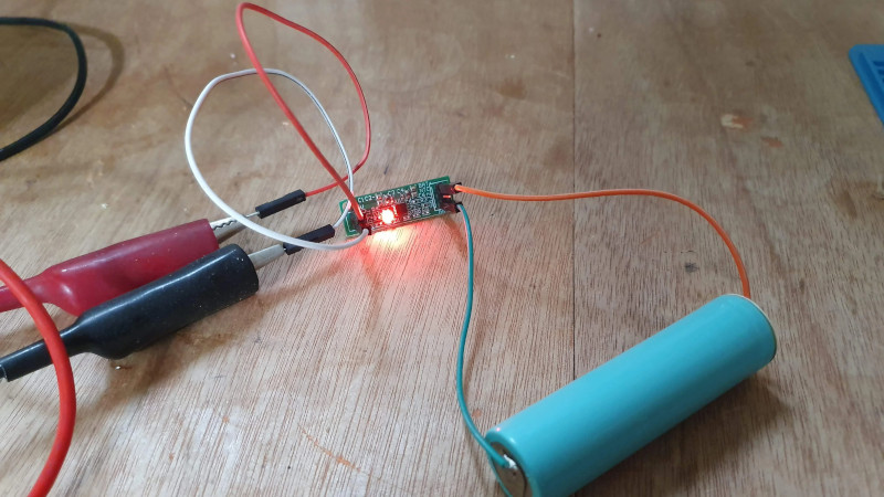
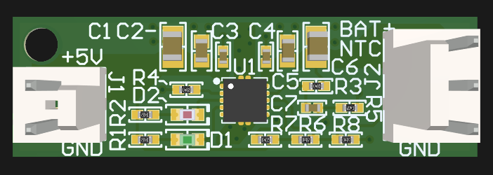 [Shahar] has implemented the design as a 33 mm X 10 mm two-layer PCB, with everything but the input and output connectors mounted to the topside. That would make this board ideal for attaching to your latest project with a dab of hot glue or double-sided tape, as there are no components on the bottom to get pulled off when you inevitably have to do some rework.
The board takes 5 VDC as the input, and charges a single 3.7 V cell (such as an 18650) at up to 1 Amp. Or at least, it can if you add a heatsink or fan — otherwise, the notes seem to indicate that ~0.7 A is about as high as you can go before tripping the thermal protection mode.
Like the boilerplate TP4056 we covered recently, this might seem like little more than a physical manifestation of the typical application circuit from the chip’s datasheet. But we still think there’s value in showing how the information from the datasheet translates into the real-world, especially when it’s released under an open license like this.


i always wanted a single board battery solution for my projects. i meant you can get chargers, switchmode supplies, bms circuits and both bare and protected batteries. but they seldom have the level of integration i want. put a battery at one end, a project at the other, provide a charging port, and just do everything including battery monitoring and online charging.
“just get a battery bank” doesnt quite give me the level of versatility im after either.
Omg, I thought I was the only person that found it strange that this doesn’t exist. A simple reference design to make your *duino or esp* project portable and battery backed. It seems al reference designs and example application circuits focus on building a charger.
There’s at least three of us!
DFRobot does this “solar manager” thing which, if you don’t attach a solar panel, does exactly this sort of thing. I’ve been looking about and I think it’s the most appropriate item I’ve found.
Currently in the article:
The board takes 5 VDC as the input, and charges a single 3.7 V cell (such as an 18650) at up to 1 Amp. Or at least, it can if you add a heatsink or fan — otherwise, the notes seem to indicate that ~0.7 A is about as high as you can go before tripping the thermal protection mode.
The “up to 1 Amp” and “~0.7 A is about as high as you can go” contradict.
How exactly do they contradict? One is the design limit of the device, and one is the practical limit if you don’t keep it cool. You even quote that qualification explicitly before proceeding to completely ignore it.
Ah, two different limits. Initially I red one limit and two maximum values.
Thanks for adding “design” and “practical” to the limits.
The problem with all “western” chips are their ridiculous prices. A quick check for the BQ24060 shows a price between USD2.6 and USD3.1 for a bare IC, while you can’t even buy a TP4056 IC from those “western stores”. (You can buy it on a PCB for EUR15).
LCSC has both IC’s in their catalog. USD2.6 for the BQ24060, or 8ct to 25ct for the TP4056, depending which version you buy.
I also tried octopart, and was surprised that it even mentions LCSC (Although only an 11ct version). It’s quite uncommon for octopart to mention LCSC, thisis the first time I’ve seen it at all.
I also find it quite absurd that these “western shops” sell single parts, especially when you go down to things like SMT resistors and capacitors, which cost milli cents. A minimum order quantity of 10 or 100 would be much more sensible for such things. A check shows you can choose between:
1 for 10ct.
10 for 2 ct each.
100 for 0.9ct each
and that goes down to 0.2ct for a reel of 5000.
I also wonder how much automation there is in such shops. I’ve seen youtube video’s of someone pushing a cart to a big rack, taking out spools and using some gadget to measure parts from cut tape. It would not be too difficult to just have a conveyor belt with boxes and have a counting and cutting device on each reel that cuts of pieces of tape which then fall into the box on the conveyor belt.
At least LCSC is doing some innovation here. They have for example an MOQ of 5 for the TP4056 and for simple SMT resitors they have a MOQ of 100 and then for a price of USD 0.0006 And yes, I had to double check the number of zero’s. So that is 6ct for a strip of 100 SMT resistors (in quite big 8085 size)
Oops typo, not 8085 resistors, but 0805.
Becouse you can have 2 resistors, in spec, true rating and exactly as ordered, day after tomorrow on your doorstep. That what we call reliable supply chain. Something LCSc have to yet lern, not everything is about the price my friend.
if america has such a reliable supply chain, why is it SO hard to move production to america?
ah yes because america doesn’t. a LOT of companies have tried, but the RELIABLE SUPPLY CHAIN is still in china. and when china’s supply chain became unreliable in 2020+, america’s was even worse.
you can literally walk around a shopping mall in shenzhen and buy the resistors you need NOW, and not in 2 days. you can even get PCBs made the same DAY, and don’t have to wait for Fedex to arrive or customs to clear it.
Heh, this comment makes me wonder if you’ve ever mass produced anything. LCSC has been 100% reliable in having good, authentic, low cost parts with excellent service in my experience.
Americans always think they are so much better at everything so it has to cost more, but at the end of the day, the extra cost just goes toward the CEO’s next yacht.
You are absolutely right my friend. Sometime I pay 30% or 50% extra in LCSC. Because the stock in Digikey is 0.
old chips on old production process’ cost more…. TI.com has 7MU+ of bq25170 available so why not just use that?
LiFePO4 support is a pretty big deal. If the TI chip offers that, and the price is close or similar to the TP4056 then that’s quite a big advantage. Don’t play it down like it’s just a minor detail.
Much like the numerous types of LiPo/LiIon cells, the charger IC still must carefully figure out the cell type for several LiFe chemistries.
For traditional LiPo/LiIon you get most conditioning / charging / safe-timeout-limits / smart-recharge-hysteresis / temperature-safety-enforcement features for $0.56.
Heavier more expensive storage with “early” charging tech is not really exciting. The LiFeYPO versions do have 1 plausible advantage in low temperatures, but for most mobile and RC use it doesn’t seem to bring a lot of value to a design (most EVs have pack-heaters to offset capacity loss with some wasted power).
Someone should do a cost study on whether is makes sense to shallow-cycle a larger liIon or use the slightly more resilient LiFe cells.
Happy computing =)
my only problem with the tp4056 is its biggest strength: its simplicity. just drop it in a circuit and it works. all it needs is a current programming resistor. everything else is pre-set. what I’d love to be able to do is set the cutoff voltage. it’s internally set to 4.2V which is 100% charge for li-ion, but I’d prefer to be able to set it to 4.0 which is around 80% charge, for significantly extended lifespan.
Looks like you can read the charging current and disable the chip when it reaches the desired charge level.
PROG(Pin 2): Constant Charge Current Setting and Charge Current Monitor Pin charge current is set by connecting a resistor RISET from this pin to GND. When in precharge mode, the ISET pin’s voltage is regulated to 0.2V. When in constant charge current mode, the ISET pin’s voltage is regulated to 2V.In all modes during charging, the voltage on ISET pin can be used to measure the charge current as follows: I = VPROG ×1200 (VPROG=1V)
CE(Pin8): Chip Enable Input. A high input will put the device in the normal operating mode. Pulling the CE pin to low level will put the YP4056 into disable mode. The CE pin can be driven by TTL or CMOS logic level.
All of the TP4056 modules I’ve found have a slightly dangerous flaw in that they can overcharge the battery. Requires a P-FET, diode, and resistor to compensate.
https://www.best-microcontroller-projects.com/tp4056.html#google_vignette
@hjf said: “my only problem with the tp4056 is its biggest strength: its simplicity. just drop it in a circuit and it works.”
Yeah but the TP4056 is not a complete solution – It has no cell protection. Look up the DW01 chip and figure out all the additional parts it will require for true cell protection when added to the TP4056. Also the TP4056 is optimal for just a single cell chemistry.
Agreed, although I’d like 85 and 90% options too
Nobody’s talking about EVs here… we’re talking about drones, RC cars, and homemade outdoor weather stations.