When you want to measure the length, breadth, or depth of an object, there are plenty of instruments for the job. You can start with a tape measure, move up to calipers if you need more precision, or maybe even a micrometer if it’s a really critical dimension. But what if you want to know how flat something is? Is there something other than a straightedge and an eyeball for assessing the flatness of a surface?
As it turns out, there is: a $15 webcam and a cheap laser level will do the job, along with some homebrew software and a little bit of patience. At least that’s what [Bryan Howard] came up with to help him assess the flatness of the gantry he fabricated for a large CNC machine he’s working on.
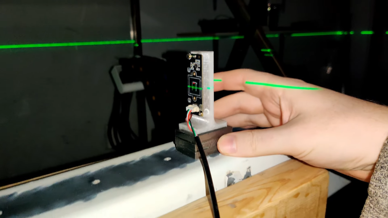
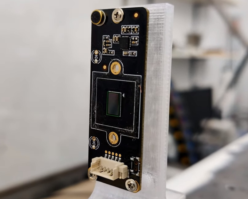 The gantry arm is built from steel tubing, a commodity product with plenty of dimensional variability. To measure the microscopic hills and valleys over the length of the beam, [Bryan] mounted a lens-less webcam to a block of metal. A cheap laser level is set up to skim over the top of the beam and shine across the camera’s image sensor.
On a laptop, images of the beam are converted into an intensity profile whose peak is located by a Gaussian curve fit. The location of the peak on the sensor is recorded at various points along the surface, leading to a map of the microscopic hills and valleys along the beam.
As seen in the video after the break, [Bryan]’s results from such a quick-and-dirty setup are impressive. Despite some wobblies in the laser beam thanks to its auto-leveling mechanism, he was able to scan the entire length of the beam, which looks like it’s more than a meter long, and measure the flatness with a resolution of a couple of microns. Spoiler alert: the beam needs some work. But now [Bryan] knows just where to scrape and shim the surface and by how much, which is a whole lot better than guessing.


I guess you’re really trusting the quality of that cylindrical lens in the laser. How would you verify *it* is good and correct?
I’ve got a similar setup that uses a molded glass lens, and it’s frankly garbage for this degree of precision. (Though fine for its actual intended use.)
Would it help to make an attempt at aligning the laser tripod exactly lengthwise with the surface that needs to be measured? That way one might be able to use “mostly” the same spot on the laser lens…
Nope, not going to help by much, he would need some kind of flat granite heavy base and then use a tripod on top of it. This would reduce many of the vibrations. Also need to use a proper laser scanner (from a laser printer is a low cost precision scanner), possible simply using a stationary laser dot would be much better and higher accuracy. Precision lab grade laser autocollimators do not use laser scanners, just a laser dot.
No, you don’t have to trust the laser. Better not trust it at all.
Or, as some popular saying: “Trust but verify”.
You can rotate the laser, for example do 4 measurements, with 90 degrees rotated each time to check for aberrations in the laser beam.
On top of that, you can also use the camera itself to measure the uniformity of the laser beam. I have not watched the video yet, but there probably is lots of room for refinement. A quick scan shows a lot of averaging is used.
I also don’t like the use of the self leveling line laser. Just a simple static laser pointer with a dot is probably much more stable. Maybe combine it with a tube to shield off most of the ambient light.
I’ll watch the whole video this evening…
I truly like this method, I was considering buying a steel ruler for DIN847/0 A ruler of 1000x60x12mmcosts over EUR300. Flatness measurements are not cheap (or cost a lot of time). This is a truly amazing hack and I wonder why I have not thought of this myself.
With a bit of hacking this is also usable for squareness measurements, in combination with a surface plate. Just put a laser pointer straight up from a surface in combination with some method to rotate it around the center axis. That does need some extra thought though.
I’m not sure if the stand for the web camera is shown in more detail. Best is of course to use a “tripod” with three protrusions at the bottom, and then place the webcam directly above one of those dots.
Oops, forgot to add…
Do a youtube search for “surface plate autocollimator” for similar devices. Prices of these are beyond hobbyist affordability.
Weird thing:
Cheap web cams have small pixels and is therefore better for this then a camera with bigger pixels.
It actually is very clever and reliable for what he is doing. Repeatability is not there for sure, but he is summing the average. This is no different than what a cmm does. Like the author said, he does not have a more reliable reference surface. And with anything accurate it is only as reliable as its reference material. He is actually getting micro and sub micron resolution. The thing is, his 50 micron resolution variance due to the self leveling laser is a lot of variance. That’s 2 thousandths of an inch. In machining… That is a fucking football field. If he said he was working with nanometers… Then OK impressive. I think his setup works and is clever. He should be congratulated for his efforts such as you should be for having a similar setup. It is reliable for what you need. And not only that, you use a fairly accurate machine to improve the accuracy of the next machine. Otherwise we are just nitpicking at the fallacy of accuracy and precision.
Well it is the deviation, you would take an average of how off the deviation accuracy it is. To do this, you would use a bed or a setup that is flat to a known value, such a granite surface plate or parallel. You can then use this low cost setup and check how off the deviation accuracy is. Then use it to flatten or scrape the beam, the deviation should correlate with the deviation accuracy measured on the beam. All in all, using photons and working down to measure in microns is an excellent way to quickly and cheaply flatten a surface than using eyeballs and other conventional ways. The webcam is measuring down to microns, some webcam can even measure down to single microns extremely accurately. He could use laser scanners extracted from laser printers, with little to no modification he would have an extremely accurate laser scanner. The laser scanner unit could be built extremely accurately, it could be mounted to a small heavy low cost lab grade (super flat) granite surface plate, this would remove many of the vibration issues.
So I’ve been continuing the work on this with a bunch of changes on order to automatically scrape with my CNC a flat surface. For the optical side I’m now using a powell lens to generate the line and a spatial filter to cleanup the laser beam. Hard to say if the spatial filter is even necessary with this setup because of how the Powell lens works. It should help produce a very sharp line over distance with very little diverging of the rays.
When I need to check for flat, I use a straightedge or surface plate *and* spotting compound (basically vaseline with dye in it, dykem “hi spot” is a popular example). You roll on a thin layer to the straightedge, apply it to the thing you are measuring and you can see the high points directly. Be careful not to scratch your nose, the dye they use is tenacious, you will have a reminder of your mistake until that bit of skin flakes off.
But this shows promise for when things get bigger, long straightedges get heavy, expensive and rare. (Basically a skinny surface plate, a 4 foot one can weigh over 50 kg, and cost upwards of $1k)
One thing that would be difficult, ensuring the laser is parallel to the surface under test. Still would show local variation.
“One thing that would be difficult, ensuring the laser is parallel to the surface under test. Still would show local variation.”
He talks about it. Divergence from the average plane of the DUT is adjusted for in the software. You need the beam to be able fall on the sensor so it needs to be within a few mm.
If confronted with the challenge, I would start with a suitable length of linear slide rail, and a dial test indicator. Use that for a quick scan. Won’t be as good as the autocolimator, etc, but it will be a lot faster. Get it to .1 mm indicated then start with the optical measurements. (I wouldn’t trust a minimally mounted slide rail closer than that, it’s going to sag more than a tenth over a meter)
Oh yea, from the Moore book, when you are measuring at gauge block accuracy levels, the guiding principle is that “everything is made of rubber”. Shift your surface gauge to another spot, or rest your palm on one spot and your master AA grade surface plate will deform. Yes, it’s a 150mm thick chunk of granite, the 1kg of the gauge, or the heat of your hand will still defect it.
An acquaintance, a retired tool and die maker (from back when you did an apprenticeship for several years) has a demo piece. He has a fairly large dial indicator that is marked for half a tenth, and it’s mounted across the diameter inside of a tool steel ring with half inch thick walls. Finger pressure on it will send the needle bouncing around.
A very simple way to reduce the apparent jitter is simply to move the auto leveling laser nearer to the gantry. Granted, the jitter will be less on the near end of the tube, but for your purposes it should be fine. I have an old line laser with manual leveling and a diy CNC with a 6’long tube steel gantry. I would like to give this a try. Thank you for aharing
Clever idea, but analyzing the result is not so simple, as you have vertical movement and/or some tilt, which is not so easy.
Another relatively cheap way of doing it is to use precision level and move it along the beam, then some curve fitting gives you the result (this is in fact pretty much the same thing).
Time for 3 pieces of box section and some lapping compound.
Always an interesting calculus on the budget of a build. I love that maybe a super cheap hack can get the job done, and saving money is saving money. But considering how costly the entire thing is, and how critical flatness seems to be, there are many traditional ways to bring something flat like scraping and a surface plate. If you don’t want a surface plate just using three rails spotted to each other will get you same results, and as a bonus you will have three perfectly straight and flat beds to use for a new build or give one to a friend or something. It requires nothing electronic and zero measuring equipment, not even a dial indicator and you can get to a sub-tenth (of a thousandth of an inch). If anyone is really really interested Foundations of Mechanical Accuracy talks about using the same methods to about 5 millionths of an inch.
I’m actually not because you can’t guarantee that it’s ground perfect. I just needed a good laser source and I had it on hand for renovations. By keeping the laser and the 1D surface you are measuring be collinear you don’t need to worry about how flat the 360 beam is. This also means that you can use a laser pointer and it works well (I’ve tried already). Laser level is really not a great source because of the wobble. I’m in the process of taking out one of the laser modules to make a better source for this tool.
That’s absolutely right and I was kinda disappointed that the webcam sensor was so big (5.9mm). It did make for a user-friendly easily disassembled package. Just had to remove some LEDs on the circuit board.
The tilt from both the laser source and the surface being measured is eloquently corrected for by using linear regression. This gives you a best-fit theoretical line through all the sample points. Then the error value from the regression line is the offset. Going over all the points and tracking their offset you can then find out how much you’d need to shim or scrape to get the surface flat. I probably should of talked about how this worked in the video but so tired with watching the baby these days. In the code, here’s where I’m doing this: https://github.com/bhowiebkr/laser-level-webcam/blob/003e17f78e2e9459275e03ede66185cf40a678a6/laser_level_tool/utils.py#L58
I’ve done similar to measure the flatness and levelness (?) of a pool table using a self leveling laser and linear array of photosensors (CCD, ILX511). So long as you keep the sensor “stick” at the same rotation, any error in tilt of the stick is relative. Flatness comes (as said) from deviation from the average plane when measurements were made at various positions across the table. Overall slate tilts were of course relative to the laser plane, itself not perfectly level but (as said) moving the laser about the table to remeasure allowed me to remove most of any laser deviation from level. Usually it was good enough for the purpose with just one position.
These days I don’t think you can find a linear array outside of Ebay and not for $5 ! Using a lens-less webcam is a nice substitute, albeit with a smaller range of deviation before the beam falls off the sensor.
Nice hack, but I’m more intrigued by the box-in-a-box section. Anyone got links to why that’s a thing?
A pure guess but I’d suggest the intention is to fill the part with sand or epoxygranite for stiffness and damping properties and still have some void to let the wires through or perhaps simply to keep the weight more reasonable.
Does seem like a strange build method to me, but that is the only reason I can come up with without some extra hints on how this thing is supposed to go together.
I talk about it in the previous video, I don’t think I’ll be getting the same properties as rotating a CFDST column on it’s side, but the composite nature of it should handle damping very well. The inclusion of the inner steel and the grout should also make it stiffer too. And also lighter the filling it fully in with grout.
Ah. I trust chat got about as far as I can throw it, but as a compositing search engine it seems to work well. Definitely food for thought, thanks
Depending on how you make use of the machine tool along with the material you’ll be cutting and a whole bunch of other variables will affect the integrity of the poured grout. Lead metal would perform better and greater mass is your friend with machine tools.
Awesome hack! That software is well thought out. That camera may have been $15 once, but is $30 now.
Some thoughts for anyone else attempting this, or similar technique.
When attempting measurements with that much precision, ensure that both the bottom of the sensor base and the gantry are spotlessly clean before placing the sensor the first time. Your fingers are sensitive. Then slide the sensor on and along without lifting it. A dust spec is big enough to throw the measurements off, but sliding the sensor base effectively plows any particles out of the way. Basically you need to use the same techniques as you would when using a surface plate. The sensor base should be ground or lapped flat to avoid it contributing errors to the results. A ground 1-2-3 block on edge could work well here.
I’m speculating that the sensor warm causes thermal expansion in the pcb. I wonder if there is a way to mount it to minimize the effects – gripping the pcb by its edges beside the sensor, letting the ends float, for example. (You could also mount it at 90 degrees but that would give up pixel count in the vertical direction, reducing the usable range.)
The self-leveling feature of the laser is unnecessary in this application – all you need is a point source that has enough co-linearity with the gantry to keep the spot on the sensor throughout the range of measurements. Theoretically (*), you could measure flatness if both were at 45 degrees to horizontal. What will make a difference is the laser base stability. Turning of the self-leveling will reduce vibrations from the laser unit itself. Giving the base mass and isolating it from the concrete slab will reduce vibrations from the environment. A small slab of granite from an old countertop (or a sink cutout from a new install) on a small tire inner-tube from a kids bike could be an affordable way to achieve this. This measurement methodology is sensitive enough to pick up vibrations from nearby road traffic. If you can’t do this, then perform the measurement at when traffic is minimized (3 am…)
(*) You can measure that flatness at 45 degrees perfectly well, but the mass of the gantry itself and the way that it is mounted affects its flatness. For this reason it’s advisable to support it at the same points in which it will be mounted in service before measuring and flattening the surface. Also, temperature variations affect flatness, so you want to stabilize that too. 68F would be standard, but if you know that your machine will always be used in a 50F room, then flattening at 50F would result in better performance. (Some European CNC manufacturers use heater/chiller units to pump fluid through their mill bases and tables to maintain consistent temperatures and ensure that they can repeatably meet some insanely tight precision).
There is a CNC maker out there that pumps refrigerant down the center of the ball screws to keep them at a constant temperature, for the same reason.
Just think about drilling a 10mm hole thru the center of a hard steel shaft that could be 5 meters long, and only 40-75mm in diameter.
Yes, although more modern designs often don’t rely on the ballscrew for positioning accuracy because no matter how well ground, installed and maintained, it is ultimately still subject to wear-induced errors. It is becoming increasingly common to find absolute position measurement feedback using linear scales with the ballscrew (or linear magnetic motor) only responsible for drive. Such designs are not subject to gear, belt or ballnut backlash affecting dimensional accuracy.
Ballscrew cooling could still be useful for increasing the rapid speeds, but introduces a rotating seal at each end of the screw which is subject to wear and failure. (Except when used on a rotating ballnut design where the screw itself remains stationary). Again, linear magnetic motors are often an easier choice if that is the concern.
This and everything you said! Agree 100% ground surfaces, 1/2/3 blocks, not lifting, clean surfaces etc… All change the results. Temperature also! But just being in the same room and moving changes the temperature. Easier method would be to bounce the laser from above on a remote gantry and sample the distances. Also he needs to set his zero and his beams in the exact same place, otherwise he is sampling different zero areas. Mind you, again he is sampling and averaging in a very clever way. It works… What can I say more. Aside from 0.002″ or 50 microns… That’s a football field of variance. On a 6 feet of length that 50 micron is meh… But on that 1 inch… That is a huge slope.
All good points. I found just simply letting the app run for a while takes care of the drift. It was more of an issue in the beginning because the tool wasn’t very optimized and would kill the battery. Now it runs very efficiently even though it’s processing a full HD stream in real time.
With some early tests using a red laser pointer, Having the sensor rotated “almost” 90 degrees away so the red beam doesn’t blow out the wires also leaves a projected line onto the sensor which acts in a similar way to the laser level without all the issues of the laser level balancing, in accurate beam projection.
It’s probably worth doing more tests with the red laser pointer in conjunction with some electronics to control the duty cycle to reduce the brightness. Also adding an IR and or ND filter will probably help with the laser pointer wavelength.
That’s true but I still want it to have the speed and be more of a router than a slow moving gantry mill. I’m running a fast 24k spindle, 400W AC servos, and prefer to be doing more high speed milling ops. Also I don’t want to deal with lead. Sounds like a real headache and I don’t want that stuff in my shop.
I’ve been using chatgpt quite extensively as a helper when programming. I used it to help write the laser level webcam tool much faster than I could of without. I love it and also hate it. It can be very frustrating to use sometimes. The best thing I find it good for is generating doc strings and commenting code into plain english for other people. It can handle simple things like generating boiler plate code but it normally falls apart when you ask it something complex. <100 lines of code is its limit before it falls apart quickly. It's also really good for optimizing code to run faster I’ve found but you gotta test everything thoroughly because it’ll through bugs into the mix all the time.
For turning a red laser dot into a line, I’ve seen people point the dot at the center of the stalk of a stemmed wine glass. If you can get a cheap one at a dollar store, you can afford to break the glass to get short sections of the stem to work with. That should get you a steady line.
I can’t even download the binary from github, virus warning (Python/Packed.Nuitka.F)
But I like the idea.
Super cheap but decently sensitive seismometer you have there!
Straightness, not flatness. The beam angle is not analyzed, hence not capturing the spiral shape.
Would benefit from less vibrations if the laser is mounted on the part to be measured.
Consider the length of the part when positioning the support legs, the entire part is going to bend from its own weight in some direction.
Hello Bryan,
impressive project and clever hack! Thank you for sharing.
By using the distribution you should get sub pixel resolution, if the laser is tight enough.
I am currently restoring a Schaublin 102VM lathe. The machine bed is longer than my straight edge. Just shifting it, does not give me a warm and fuzzy feeling…
Your project kicks in here at the right time and the right concept. I ordered a laser and camera, so I will give it a try soon! If I can get the machine bed flat to 1/100mm I will be really happy. Then comes the sliding support, Y and Z matter, so I will have to fiddle with the laser… But this should de ok, as long as I have at least one straight edge, and this can be the machine.
From my point of view: it is an enhancement to a straight edge and scraping, not a substitute.
I will keep you updated,
thank you very much for you effort of programming all this and making it public.
Greetings from Germany
Georg