It might seem like 3D printing is a thoroughly modern technology, but the fact is, it’s been used in the industry for decades. The only thing that’s really new is that the printers have become cheap and small enough for folks like us to buy one and plop it on our workbench. So why not take advantage of all that knowledge accumulated by those who’ve been working in the 3D printing field, more accurately referred to as additive manufacturing, since before MakerBot stopped making wooden printers?
That’s why we asked Eric Utley, an applications engineer with Protolabs, to stop by the Hack Chat this week. With over 15 years of experience in additive manufacturing, it’s fair to say he’s seen the technology go through some pretty big changes. Hes worked on everything from the classic stereolithography (SLA) to the newer Multi Jet Fusion (MJF) printers, with a recent focus on printing in metals such as Inconel and aluminum. Compared to the sort of 3D printers he’s worked with, we’re basically playing with hot, semi-melted, LEGOs — but that doesn’t mean some of the lessons he’s learned can’t be applied at the hobbyist level.

The Chat started off with questions about what Eric’s day-to-day looks like, and what kind of awesome machines he gets to play with. After all not many of us will get access to a printer that can spit out something the size of a car engine, so we’ve got to live vicariously through others more fortunate than ourselves. This lead to something of a primer about the different printing technologies currently in use by the “Big Boys” for both plastic and metal parts.
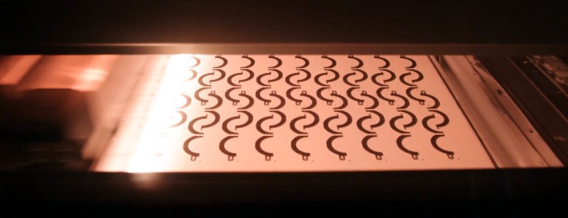
Rather than fused deposition modeling (FDM), the process by which our desktop printers work, Eric says most of the time he’s dealing with some form of sintering. There’s several reasons for this, but one of the major ones is speed. Since there’s no time penalty for printing multiple objects, they can load the entire print surface up and maximize their efficiency. In one case Eric recalls they ran off 3,000 individual parts in a single 48 hour print.
Eventually the discussion moved on to the actual design of parts destined for a 3D printer, which is where things were arguably the most applicable for home gamers. Eric mentioned that sintering and jet fusion printing doesn’t require supports, as the powdered plastic itself provides a sort of scaffolding for the part as it’s being built up. But even if the part is being produced with a technology that would require support material, good designers try to avoid it as much as possible. Especially in the medical and aerospace fields, where internal supports could pose problems. As it turns out the rules here are pretty similar to what those of us with desktop machines are used to, such as making sure to keep angles steeper than 45°, and using chamfers in place of hard edges.
Interestingly, Eric says one of the biggest problems they have is with wall thickness. Obviously there’s a minimal wall thickness for each different combination of material and printing technology, but more than that, he says rapidly varying the wall thickness of a printed metal part can lead to differential shrinkage which can compromise the whole part. If you can’t use a consistent wall thickness through your design, his recommendation is to make the transitions as gradual as possible, for example by using fillets.
It was also somewhat comforting to hear that, even with high-end industrial 3D printers, there are still dimensional accuracy issues to contend with. Case in point: holes on the side of objects. Eric says openings on the top and bottom aren’t so much of a problem since they’re essentially a stack of two-dimensional shapes, but once you have the a hole on the side of the object, the layer height of the print adds a new variable. The problem is serious enough that, if a part needs holes on the side, it will often be handled in an additional processing step: plastic parts will have the holes drilled after printing, and metal ones will have the openings machined to the proper tolerances. Just like at home!
In fact, for metal parts, there’s usually a fair amount of machining required after they come off the printer. Eric says that even in the best case, they shoot for a metal part to be 95% complete when the print is done. From there, it almost always needs a trip to the machine shop to be cleaned up. But he also says this isn’t really a quirk limited to 3D printing, and that cast metal components often need a similar level of post-processing to get the details right. As a side-effect, he notes that those who have experience designing parts for casting tend to do well when switching over to additive manufacturing.
We’d like to thank Eric for taking the time to join us this week in the Hack Chat. While we might never get to work on the class of machines at his disposal, we enjoyed hearing about the little details they have in common with our far more simplistic desktop printers — there’s a certain satisfaction in knowing even the pros occasionally struggle with the same issues we do.
The Hack Chat is a weekly online chat session hosted by leading experts from all corners of the hardware hacking universe. It’s a great way for hackers connect in a fun and informal way, but if you can’t make it live, these overview posts as well as the transcripts posted to Hackaday.io make sure you don’t miss out.


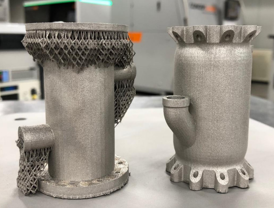
If you are going to do a comparison of a standard part and a part designed for 3D printing, you really need to keep the functionality the same or explain why the new model is more suitable. Having the pipe come out curved and end up parallel with the main body may make it easier to print but could alter the functionality of the piece quite significantly.
Also look at the holes that are presumably for bolts, having a bolt or nut clamping on a slanted surface isn’t going to produce great results, it would however be fine if the holes were tapped and bolted from the other side. The gaps between the holes could create issues as well with clamping or sealing.
There is no reason that the top and bottom couldn’t remain as full circles, even with the chamfer on the top section. There is also no need for the chamfer on the bottom section, it won’t make it print any better and will reduce any material savings from having gaps between the holes.
Also you can see that the new model expands in the middle and shrinks again at the end, that could change the properties of the fluid going into or out of the side tubes.
Designing for 3D printing does not mean modifying key properties of the original design.
Having been exposed to a lot of professional FDM/AM through trade shows and white papers, I came to the realization that many of them have no idea what they’re doing or talking about. I guess it’s true that additive manufacturing is in need of talent at the industrial level, because it seems that there are so-called engineers working in AM who don’t have a grasp of basic mechanical engineering concepts.
I have 8 years of additive experience and 3 running a large scale print farm in Central America. We print exclusively real life applications and usually run around 100-150 kilos of mixed filament per month.
Interviewing someone like myself of another consumer facing print farm would be more beneficial. No offense to the application engineer here but as with many people in tradeshows they have vast knowledge of the materials and their logical application but that does not translate to real world modern use cases especially in the consumer oriented space.
This is usually a Design For Manufacture issue. The examples are not making a part that is fungible with an existing part, but rather designing a part to do some task, for use in an environment where this part _is_ the expected part (usually because the job came after the part was designed, but sometimes it’s simply that the job isn’t sensitive to these changes, so the part designer changed things to make a cheaper or more reliable part that would still get the job done)
Clearly, the part in question does the intended job, or there wouldn’t be a market for it (and its manufacturer would rapidly go bankrupt), so we can assume that’s not what’s happening.
Or the part in this example was just made as an example.
Or maybe the function of the part is only to demonstrate ways to change an object so it prints easy, not to be clamped or carry fluid. It might not be easy to find 1 part that needs many modifications, so they are combined in a bogus part just for the video.
Your comment is 180 degrees wrong. The original part was not optimised for it’s function. It was optimised for low cost manufacture from standard plate and tube stock welded together.
It’s design may be “adequate”. It is more heavy and restrictive than it could be. It was however cheap-ish to make.
The new part is also optimised for it’s manufacturing process constraints, but with a lot fewer constraints it can perform better, or the same using less material or space.
My comment is not wrong at all. Yes the original was made to be easy to manufacture but it also has very different and beneficial properties that the 3D printing optimized solution does not have.
There is nothing to say that the 3D printing optimized part isn’t heavy and restrictive either. Yes the 3D printed parts could be made to perform better than the original part but not when it is getting optimized for printability like it is here.
I never denied that the part could be made better than the original, just that the 3D printing optimized part they show here isn’t a good way of doing it and is significantly changing the properties of the original design.
The plural of LEGO is LEGO.
False. Plural of Lego is Lego Bricks.
And consider supporting them on Thangs :)
I guess the parts are only made as an example for some details, because they are different in function and i see mechanical and functional issues with the “enhanced” support free version.
Pros never consider themselves a pro, simply knowledgeable on a subject with plenty left to learn.
Any time I see learn from a pro I cringe.