When USB first came on the scene, one of the benefits was that essentially any four conductors could get you to the point where you could send information at 12 Mbps. Of course everything is faster these days, and reaching today’s speeds requires a little bit more fidelity in the cables. This simple tester makes sure that your modern cables are actually up to the task.
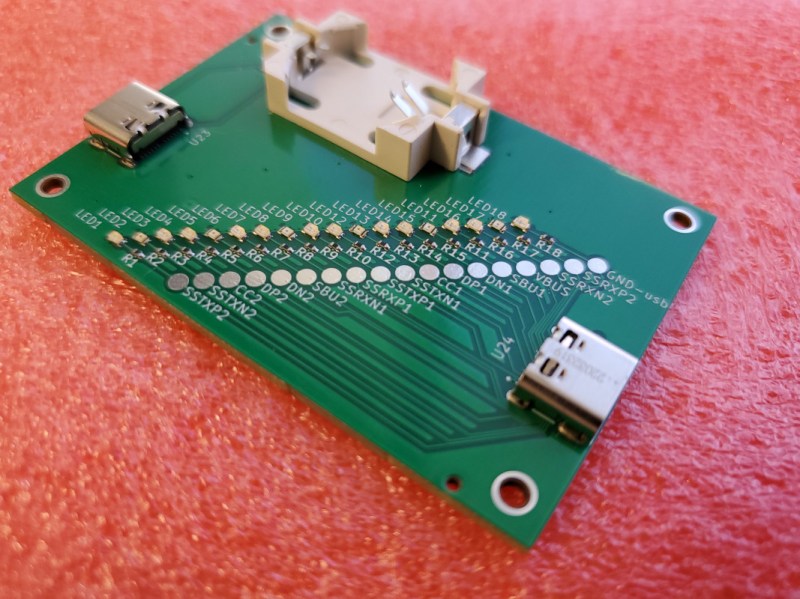
One of the design goals of this project is to automate away the task of testing cables or finding one that works, especially before thinking a problem with a device is somewhere in software, spending hours or days debugging, before realizing that it’s actually being caused by a hardware malfunction. The small PCB has two USB-C fittings to plug in both of the ends of a cable to, and between those connectors there is a number of LEDs. Each LED is paired to one the many conductors within the USB cable, and not only does it show continuity of these conductors but it can also show a high resistance connection via a dimly-lit or off-color display from an LED.
One of the other interesting facets of this build is the use of JITX, which is a software-defined electronics CAD tool which allows PCB design to be automated by writing out the requirements of the PCB into code, rather than drawing it manually. It’s worth a look, and a lot of the schematics of this particular project as well as some discussion on this software can be found on the project’s GitHub page. Incidentally, if this tester looks familiar, it’s probably because your’re thinking of the open source hardware USB tester created by [Álvaro Prieto].


But what about a cable with the pins connected in the wrong way? Like the one that fried the laptop of one Google engineer because it swapped the power pins in one of the connectors, IIRC.
Oh thats easy those have a smoke indicator
SED, Smoke Emitting Diode
Meh. This is really only useful for checking if there’s continuity, nothing else. For proper testing, you’d measure the resistance of the individual lines and check that they’re within spec and then measure crosstalk between the lines as well.
Sometimes checking if the wire is there will get you 90% of what you need. I would kill for one of these that does all pins and shell of USB c, and also has USB a b micro mini on one of the sides for checking USB c -> everything else
There are commercial devices that can send a high frequency signal and check it, but they are all expensive as heck.
I just have a bundle of spare cables.
Australian electronics magazine “Silicon Chip” published a design for just such a device in 2021. I bought the kit and love it. https://www.siliconchip.com.au/Issue/2021/November/USB+Cable+Tester+%E2%80%93+Part+1
Meh. That sounds like a lot of work when all you care about is continuity
This is bad. Its not useless, because its good for one thing: is the pin connected to something. But this won’t reveal wrong connections, or pins connected to multiple pins, shorts, etc.
A better solution would be what the old school ethernet cable testers do. A timer + a shift register powers the pins one by one then you check that exactly one led lights up at a time. With USB-C this would not be the case for all pins (shields are internally connected for example) but one can learn the “good” pattern.
It would identify cables that only have the power wires yet incorrectly have the USB logos on them. The USBIF specifies that their logos are not to be used on charging only cables. If it can’t transfer data it’s not a USB cable.
Is this OpenScad for PCB design? People are going to have feelings.
I like this idea for older generations of USB cables or A to C cables. For C to C cables I want not only continuity checked but also tell me if it’s E-marked and if it is read out the data from the e-mark and tell me what it’s capable of. I’m sure someone smarter than me could get a cheap microcontroller paired with a character display to do this.