If you follow audiophile reviewers, you’ll know that their stock-in trade is a very fancy way of saying absolutely nothing of quantifiable substance about the subject while sounding knowledgeable about imagined differences between devices that are all of superlative quality anyway. If you follow us, we’ll tell you that the only reviews that matter are real-world measurements of audio performance, and blind listening tests. We don’t have to tell you how to listen to music, but perhaps it’s time in our Know Audio series to look at how audio performance is measured.
Before reaching for the bench, it’s first necessary to ask just what we are measuring. What are the properties which matter in an audio chain, or in other words, just what is it that makes an audio device good?
Why Does A Rock Guitar Sound Angry While A Classical Guitar Doesn’t?
There are of course many things than can be measured, but the one which matters the most in this context is probably distortion. You’re probably used to distortion in music, while a classical guitar sounds like a string being plucked, a rock guitar sounds… angry.
This is because the rock guitarist uses an effects pedal which induces audible distortion onto the otherwise pretty clean guitar sound. There are many different guitar effects pedals to be found, but some of the simplest merely drive an amplifier into clipping to make something closer to a square wave. But to understand what’s really going on, it’s necessary to look at the waveform not in the time domain as a sine wave or a square wave, but in the frequency domain as a spectrum.
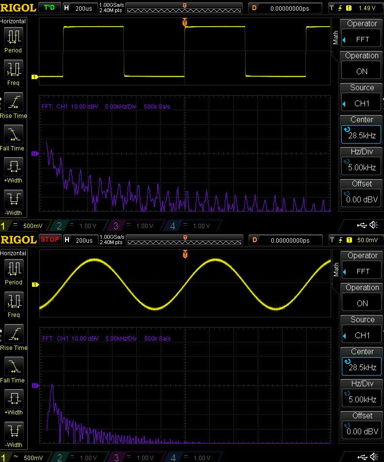
If you were to take a perfect sine wave oscillator and plug it into a spectrum analyser, you would expect to see a single peak corresponding to the frequency of the sine wave. If you apply distortion to that sine wave, the spectrum analyser would start to show peaks at other frequencies depending on what type of distortion is being applied.
It’s a subject we’ve looked at in detail here at Hackaday in the past, and we’re guessing that many of you will be familiar with the mathematical derivation of a square wave from a series of harmonic sine waves. Distortion in an audio device is measured by looking at these extra peaks in the spectrum, and is expressed as either a dB value or a percentage indicating their relative strength compared to that of the original signal. For those guitar pedals the figure will be in the tens of percent, while for a good quality audio amplifier it will be only a fraction of a percent. It’s also usual to see the figure quoted as THD+N which indicates the noise component in the rest of the spectrum, as well as seeing it quoted for a single (usually 1kHz) frequency.
Measuring distortion is a superficially simple process, but in practice constructing an instrument to do so effectively is not an easy task. A device under test is fed with as pure a sine wave as can be generated, and the RMS voltage of its output is measured both directly from it and through a notch filter which removes the fundamental frequency of the sine wave. The idea is that the filtered signal returns only the component of the output which is due to the distortion, and thus can be compared to the full figure to derive that relative figure.
The designer of the instrument thus has several significant hurdles to overcome, because not only must their oscillator and filter be as near perfect as can be attained, but the rest of their analogue signal chain must not contribute to the distortion being measured. This is made even more difficult by a typical instrument requiring these characteristics across a wide frequency range; if a single frequency filter is a challenge then a variable one is much more so. A modern audio analyser will typically be a computer-controlled combination of digital and analogue instrumentation with the oscillator and measurements replaced by a very high quality DAC and ADC, while the filter retains an analogue circuit.
From A Light Bulb To The Digital Domain
The first HP product was the HP200A, a high quality audio oscillator that famously had an incandescent bulb as a non-linear element in its circuitry as a means to stabilise the amplitude and thus reduce the distortion of its output. This idea forms the basis of subsequent steps to reduce oscillator distortion, with improved feedback and AGC circuits.
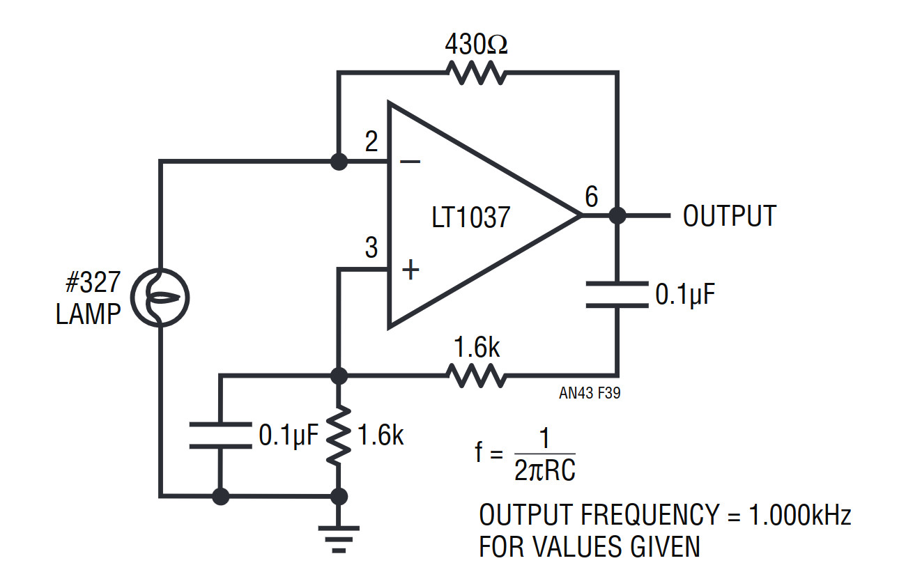
It’s suggested that you read Linear Technologies app note 43, in which Jim Williams delivers a comprehensive introduction to this topic, and then Cheng-We Pei’s note on a low distortion oscillator using an RMS-to-DC converter in its feedback loop.
Unfortunately, most inexpensive benchtop function generators don’t provide this low level of distortion, either relying on a low-pass filter to distort a square wave into something approximating a sine wave, or using a simple DAC for digital synthesis, so for audio measurement it’s worth looking for an unloved older analogue oscillator.
HP continued making derivatives of the 200A for many decades and innumerable companies produced clones and copies, so it’s comparatively easy to find older oscillators on the second-hand or surplus market.
The rest of the components are somewhat more difficult to find, because those filters are expensive to produce and thus an audio analyser can be an eye-wateringly expensive device. Even older instruments hold their value, and I consider myself exceptionally lucky to have secured my all-analogue 1970s-era HP334A distortion analyser without parting with the GDP of a small country. Given a suitably high quality ADC it’s possible to take the approach of filtering in the digital domain, however this may be beyond the capabilities of a mundane sound card. I investigated this idea a few years ago in an April Fool post about gold cables, and though the cable was a joke it’s still a valid measurement technique to which I might return in due course.
So this should have served as a basic primer in audio distortion and why it’s important to consider for your listening pleasure. There will be a further Know Audio piece on distortion to follow, in which we take a look at real-world distortion measurements and take a closer look at the instruments.


I take issue with your comment:
“..the only reviews that matter are real-world measurements of audio performance, and blind listening tests.”
As my hearing has degraded over the years, I find I can enjoy music as much as in my youth with equipment that is objectively pretty crappy.
The only reviews that REALLY matter are your own subjective listening tests.
Yes. But in this context I was talking about third-party reviews.
True. But if you’d be an audiophile, you (a) wouldn’t listen to music, only to sound quality and (b) you’ve arrived in a price segment where you will have a hard time to tell the audiophile difference between two a $6000 and a $8500 power cord. So the audiophile absolutely requires confirmation through 3rd party reviews, to be assured to own the best possible power cord. Well, until a review for the $17,200 “Purist Audio Design 30th Anniversary Power Cord” comes up.
Now, that may sound funny and sounds suspiciously like it confirms what you wrote…but you miss one point. Commercial audio equipment (especially the expensive stuff) doesn’t just sell audio quality but also a warm fuzzy feeling. The typical Bose owner is happy, not because the sound is great but because the owner is constantly reminded though a massive advertising campaign that the owned product is the best money could have bought. *That’s* where customer satisfaction comes from! It also helps that Bose tried to forbid product comparisons and independent reviews (if you want to sell Bose in your audio store, you’ll sign a contract that a buyer must be prevented to compare Bose with competitors; that’s why you often see Bose never near competing audio systems).
And, especially in the Bose case, it’s nice to have independent reviews and system measurements. Yes, you can try to compare the tiny Bose “surround-with-only-two-speakers” system against the competitors systems which is 100ft away, but you’ll still be tricked (you can’t adjust the volume on the Bose system so it’ll blast at you full power, and your ears will be less precise — and there’s also the hidden third speaker…)
https://archive.org/details/SlippermansRecordingDistortedGuitarsFromHellreadableVersion
I’ve got an HP 339A and it’s a fine instrument. Although most folks are measuring distortion to come up with a percentage number, I find that it’s a really great design tool. The way it works is it has a very spectrally pure tone oscillator and a deep narrowband notch filter that additionally has an output of all of the audio after the notch, i.e., the output of only the distortion. This is the powerful part. I connect an audio amplifier to listen to this and an audio spectrum analyzer to this output.
You can easily determine what the source of distortion is. You can see power supply ripple, see crossover distortion, second and third order harmonic distortion (nonlinear amplification) It helps you determine the source of distortion to reduce it further in real time when you change cable routing, tube (valve) bias changes, etc.
I once did a design using a single chip headphone amplifier with a single ended power supply, capacitor output coupling. It was okay with about a fraction of a percent of distortion, but it showed that the source of the distortion was output transistor crossover distortion. You might not think you could do anything about it, being a single audio chip, but I found that putting in a 1K resistor to ground from the DC offset output forced the chip to constantly run current through the finals and increase the Q point bias current. It lowered the distortion by about 1/100th what it was before the resistor.
Distortion meter as a design tool.
Very much agree on the after-the-filter bit. Mine’s a 334, so no oscillator built in, but yes.
What is it that makes the sound of electric guitars (or sound from phone speakers) so painful to listen to to soem people (me) even when at low volumes?
Rich content of odd harmonics, higher frequencies, plus resonance on some of them and your taste. Some electric guitar distortion sound very warm and pleasing other are aggressively annoying.
Years back when my little sister was just getting her driver’s license, I mentioned how having a car is such a rite of passage and symbol of freedom for teenagers, I think the resemblance of a distorted guitar to the sound of an engine might partially explain why so many teens also gravitate towards rock music, many of us having ignored it as younger children.
“Okay, so I’ve heard of distortion pedals and stuff, but what exactly does that mean?”
I promptly fetched my copy of Pink Floyd’s Pulse album, sat her down in front of the stereo, and played Sorrow.
Ten minutes later, we both emerged from the trance, and she just kinda blinked a me a few times, speechless. A moment to ponder, then… “Okay, yeah. I get it.”
might explain why it seems like rock music has declined in popularity too. Newer cars are quieter and fewer teens seem particularly interested in them
from a players perspective,(mine),its not distortion unless its unintentional
as a listener any sound that I dont like ,distorts my mood
and if its a hardware based ugly sounds,I fix it to my satisfaction, if its “programing” that I dont appreciate,there is a button for that
in a former life I was a recording engineer and was completely imersed in audiophile everything and learned
that in the dawn times there were attempts to create the highest possible fidelity and headroom in recordings
this was done very simply by massivly increasing the speed
of the tape drives ,more tape per second is the analog version of a higher bit rate,the accounts are that it worked exceptionaly well,but that there was no way to comercialise
it
my personal recording philosophy is to whip the band and all of there gear into shape and go live to two track
nothing goes down that is not real
Thanks Jenny for a great no-nonsense article.
Side note.
Plugs guitar into distortion pedal. Records it with as low distortion as possible and plays back with as low distortion possible. Seems somehow like gloriously circular logic.
Not at all. The guitar setup is PROducing music — whatever the artist/producer wants it to sound like is fine. Playing back is REproducing music, and any added distortion gives you something the original artist didn’t intend. That’s why overdriven amps are fine for guitars, but not for use in your living room music system.
my recipe is amp clip and amp again. sounds monstrous and crunchy. made palm muted thrash riffs very easy to get right. just using a vouple opa705s. probibly not the best opamp for audio, but it works.
“you’ll know that their stock-in trade is a very fancy way of saying absolutely nothing of quantifiable substance about the subject while sounding knowledgeable about imagined differences”
Much like wine tasters.
B^)
Yet there sometimes floats by a set of electrostatic speakers. In a sea of unicorn horn cables and bullshit.
To be fair, electrostatic speakers can be great. But they’re no panacea.
Sure. But if you’re spending the price of a house on a pair of speakers, you will build a good room to listen to them in.
The only speakers comparable on highs are plasma. Which aren’t much use except at over 10kHz.
Instead of plasma, what about magnetostatic, or maybe piezo since IIRC the modern cheap ultrasonic transducers by nature don’t have any resonances in the audible range, which was one of the old problems with the idea?
The point of electrostatics is one speaker per side. Nothing can compare on highs except plasma, but also insanely great lows and mids. Price of a cheap house.
The speakers are their own crossovers. Basically 2D transmission lines. The films resistance is adjusted to control how much surface responds vs freq.
THD for most good speakers is in the 1% range. (Which makes spending money to move the decimal point on other components pretty stupid). THD for electrostatics is 0.0x%…Until the film hits the charged grill…THD remains a shitty metric for music…I digress.
Giant piezo holds promise. Will need a subwoofer even if scaled to the size of electrostatics. Just on motion limit. That size piezo is going to cost too much…Their were plans for piezo layers in displays. Whole screen is speaker. Never made market to my knowledge.
Audiophiles say electrostatics are ‘cold’.
“Unfortunately, most inexpensive benchtop function generators don’t provide this low level of distortion, either relying on a low-pass filter to distort a square wave into something approximating a sine wave”
That frequency domain would be tricky to implement. It would require low pass filters that track the output frequency over many decades.
The traditional technique, as embodied in the ICL 8038 and successors, is time-domain wave shaping. The TLDR is to use diode-resistor networks to distort the output voltage so that a triangle wave becomes more like a sine wave. The tell-tale is visible on a scope: a small “nipple” at the peak/trough of each cycle.
The ICL8038 would typically make a sinewave with 1% or 2% distortion. Maxim made the MAX038, which when I used it seemed to be better behaved, but the datasheet shows about 1.8% distortion typically.
Texas Instruments has an ap note for “log” shaping of a triangle into a sine, good for about 0.4% distortion. My own SPICE experiments to do more complicated shaping indicated that about 0.1% is possible. Trying to do better than that runs into problems with matching, temperature coefficients, and precision components.
What happened to just using as many op amp integrators as needed on the original approximation?
IIRC each one gets cleaner. Usual caveats, keep of rails etc.
“There will be a further Know Audio piece on distortion to follow, in which we take a look at real-world distortion measurements and take a closer look at the instruments.”
I hope you’ll also discuss TID, which – in the 70s – the hi-fi world regarded as an advanced topic worthy of many articles in the magazines. Being dependent on the output level, simple measurements missed it accidentally (amateur reviewers) or deliberately (amplifier manufacturers).
If they had had a scope, the onset and principal cause would have been obvious: slew-rate limiting in the amplifier.
Good example of the lamp as a nonlinear resistor. It was standard design in audio oscillators at the time. I had one in an Eico oscillator.
It has nothing to do with distortion other than to level or clamp the loop gain to keep within the linear area of the amplifier.
As compared to back to back diode limiters (another way of limiting loop gain) they’re very linear for audio.
Negative feedback gets you only so far. Good low distortion oscillators have pretty low noise and very linear amplifiers with very low crossover distortion and careful attention to power supply filtering.
It’s the difference between a 1% audio oscillator (Eico) and a 0.001% THD oscillator (HP).
I’ve used an HP 200A, and while the distortion may be OK at 1 kHz, it’s not at 20 Hz. At low frequencies the thermal time constant of the light bulb interacts with the oscillator, yielding a waveform that is pretty funny looking.
Ultra-low distortion sinewave generation can be difficult. Scouring the internet for designs provides a few that are good for 1 PPM distortion or better for a single frequency. These oscillators are Wien bridge or state variable or other similar designs, not triangle shapers. The single frequency means that the amplitude control mechanism can have a fixed response time.
Making an oscillator that can be tuned over 3 decades, or even 1 decade, runs into problems. Unless tuning and amplitude control components track perfectly, each change in frequency means that the amplitude has to be given time to settle to a constant value. Making the amplitude settle rapidly means that the amplitude control introduces distortion.
I think that the only practical way to make a sinewave generator with 1 PPM distortion, rapid settling, and 20 Hz – 20 kHz range is digital synthesis. There are audio DACs now good for 24 bits and some microcontrollers are capable of driving those DACs.
Instead of plasma, what about magnetostatic, or maybe piezo since IIRC the modern cheap ultrasonic transducers by nature don’t have any resonances in the audible range, which was one of the old problems with the idea?
Looks like I got struck by the comment glitch again.