When thoughts turn to the modernization and decarbonization of our transportation infrastructure, one imagines it to be dominated by exotic materials. EV motors and wind turbine generators need magnets made with rare earth metals (which turn out to be not all that rare), batteries for cars and grid storage need lithium and cobalt, and of course an abundance of extremely pure silicon is needed to provide the computational power that makes everything work. Throw in healthy pinches of graphene, carbon fiber composites and ceramics, and minerals like molybdenum, and the recipe starts looking pretty exotic.
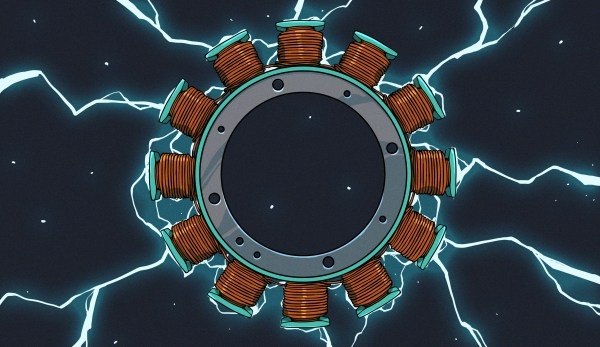
As necessary as they are, all these exotic materials are worthless without a foundation of more familiar materials, ones that humans have been extracting and exploiting for eons. Mine all the neodymium you want, but without materials like copper for motor and generator windings, your EV is going nowhere and wind turbines are just big lawn ornaments. But just as important is iron, specifically as the alloy steel, which not only forms the structural elements of nearly everything mechanical but also appears in the stators and rotors of motors and generators, as well as the cores of the giant transformers that the electrical grid is built from.
Not just any steel will do for electrical use, though; special formulations, collectively known as electrical steel, are needed to build these electromagnetic devices. Electrical steel is simple in concept but complex in detail, and has become absolutely vital to the functioning of modern society. So it pays to take a look at what electrical steel is and how it works, and why we’re going nowhere without it.
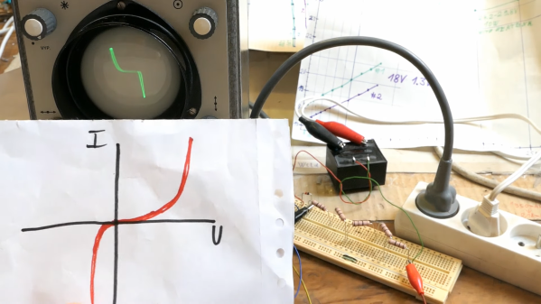
To a lot of us, curve tracing seems to be one of those black magic things that only the true wizards understand. But as [DiodeGoneWild] explains, curve tracing really isn’t all that complicated, and it doesn’t even require specialized test instruments — just a transformer, a couple of resistors, and pretty much whatever oscilloscope you can lay your hands on.
True to his handle, [DiodeGoneWild] concentrates on the current-voltage curves of Zener diodes in the video below, mainly as a follow-up to his recent simple linear power supply project, where he took a careful look at thermal drift to select the best Zener for the job. His curve tracer is super simple — just the device under test in series with a bunch of 10-ohm resistors and the secondary winding of a 12-volt transformer. The probes of his oscilloscope — a no-frills analog model — go across the DUT and the resistor, and with the scope in X-Y mode, the familiar current-voltage curve appears. Sure, the trace is reversed, but it still provides a good visualization of what’s going on. The technique also works on digital scopes; just be ready for a lot of twiddling to get into X-Y mode and to get the trace aligned.
Of course it’s not just diodes that can be tested with a curve tracer, and [DiodeGoneWild] showed a bunch of other two-lead components on his setup. But for our money, the neatest trick here was using a shorted bridge rectifier to generate a bright spot on the curve to mark the zero crossing point. Clever indeed, and pretty useful on a scope with no graticule.
Since their relatively recent appearance on the commercial scene, rare-earth magnets have made quite a splash in the public imagination. The amount of magnetic energy packed into these tiny, shiny objects has led to technological leaps that weren’t possible before they came along, like the vibration motors in cell phones, or the tiny speakers in earbuds and hearing aids. And that’s not to mention the motors in electric vehicles and the generators in wind turbines, along with countless medical, military, and scientific uses.
These advances come at a cost, though, as the rare earth elements needed to make them are getting harder to come by. It’s not that rare earth elements like neodymium are all that rare geologically; rather, deposits are unevenly distributed, making it easy for the metals to become pawns in a neverending geopolitical chess game. What’s more, extracting them from their ores is a tricky business in an era of increased sensitivity to environmental considerations.
Luckily, there’s more than one way to make a magnet, and it may soon be possible to build permanent magnets as strong as neodymium magnets, but without any rare earth metals. In fact, the only thing needed to make them is iron and nitrogen, plus an understanding of crystal structure and some engineering ingenuity.
On today’s episode of “Will it MIDI?” we have the common slide whistle. Spoiler alert: yes, it will, and the results are just on the edge of charming and — well, a little weird.
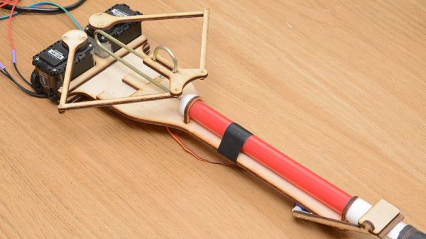
As maker [mitxela] points out, for all its simplicity, the slide whistle is a difficult instrument to play. Or, at least a difficult one to hit a note repeatably. It’s a bit like a tiny plastic trombone, in that both lack keys or stops that limit the vibrating column of air to a specific length. Actually, the beginning of the video below shows a clever fix for that problem on the slide whistle using magnets, but that’s mainly a side project.
[mitxela]’s MIDI-fication of the slide whistle required a bit more than a few magnets. To move the slide to defined positions, a pair of high-precision servos was connected by a laser-cut plywood scissors linkage. The lung-power of the musician is replaced by a small electric blower, mounted away from the whistle and supplying air through a long hose. The fan’s speed, and therefore the speed of the airflow, can be varied; this prevents low notes from shifting up in register from over-blowing, if that’s the right term. Another servo controls a damper that shuts off the flow of air from the mouth of the whistle to control notes without having to turn off the fan completely. The main article goes into detail about the control electronics and the calibration process.
The video has a few YouTube copyright strikes demo songs, and we have to say we’re impressed with the responsiveness of the mechanism. Some will object to the excess servo noise, but we found it nice — almost like guitar string-squeak. We like the tunes where [mitxela]’s servo-plucked music box joined in, too.
There is an old saying: “In theory, theory and practice are the same. In practice, they are not.” We spend our time drawing on paper or a computer screen, perfect wires, ideal resistors, and flawless waveforms. Alas, the real world is not so kind. Components have all kinds of nasty parasitic effects and no signal looks like it does in the pages of a text book.
Consider the following problem. You have a sine wave input coming in that varies between 0 V and 5 V. You want to convert it to a square wave that is high when the sine wave is over 2.5 V. Simple, right? You could use a CMOS logic gate or a comparator. In theory…
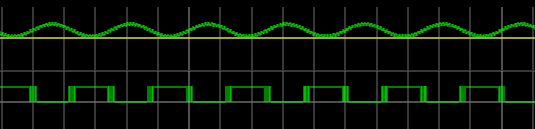
The problem is, the sine wave isn’t perfect. And the other components will have little issues. If you’ve ever tried this in real life, you’ll find that when the sine wave is right at the 2.5 V mark the output will probably swing back and forth before it settles down. This is exacerbated by any noise or stretching in the sine wave. You will wind up with something like this:
Notice how the edges of the square wave are a bit fat? That’s the output switching rapidly back and forth right at the comparator’s threshold.
Hysteresis
The answer is to not set the threshold at 2.5 V, or any other single value. Instead, impose a range outside of which it will switch, switching low when it leaves the low end of the range, and high when it exceeds the high end. That is, you want to introduce hysteresis. For example, if the 0 to 1 shift occurs at, say, 1.9 V and the 1 to 0 switch is at 0.5 V, you’ll get a clean signal because once a 0 to 1 transition happens at 1.9 V, it’ll take a lot of noise to flip it all the way back below 0.5 V.
You see the same effect in temperature controllers, for example. If you have a heater and a thermal probe, you can’t easily set a 100 degree set point by turning the heater off right away when you reach 100 and then back on again at 99.9999. You will usually use hysteresis in this case, too (if not something more sophisticated like a PID). You might turn the heater off at 99 degrees and back on again at 95 degrees, for example. Indeed, your thermostat at home is a prime example of a system with hysteresis — it has a dead-band of a few degrees so that it’s not constantly turning itself on and off.
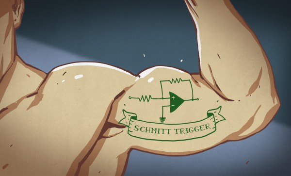
Schmitt Triggers and How to Get One
A Schmitt Trigger is basically a comparator with hysteresis. Instead of comparing the incoming voltage with VCC / 2, as a simple comparator would, it incorporates a dead band to ensure that logic-level transitions occur only once even in the presence of a noisy input signal.
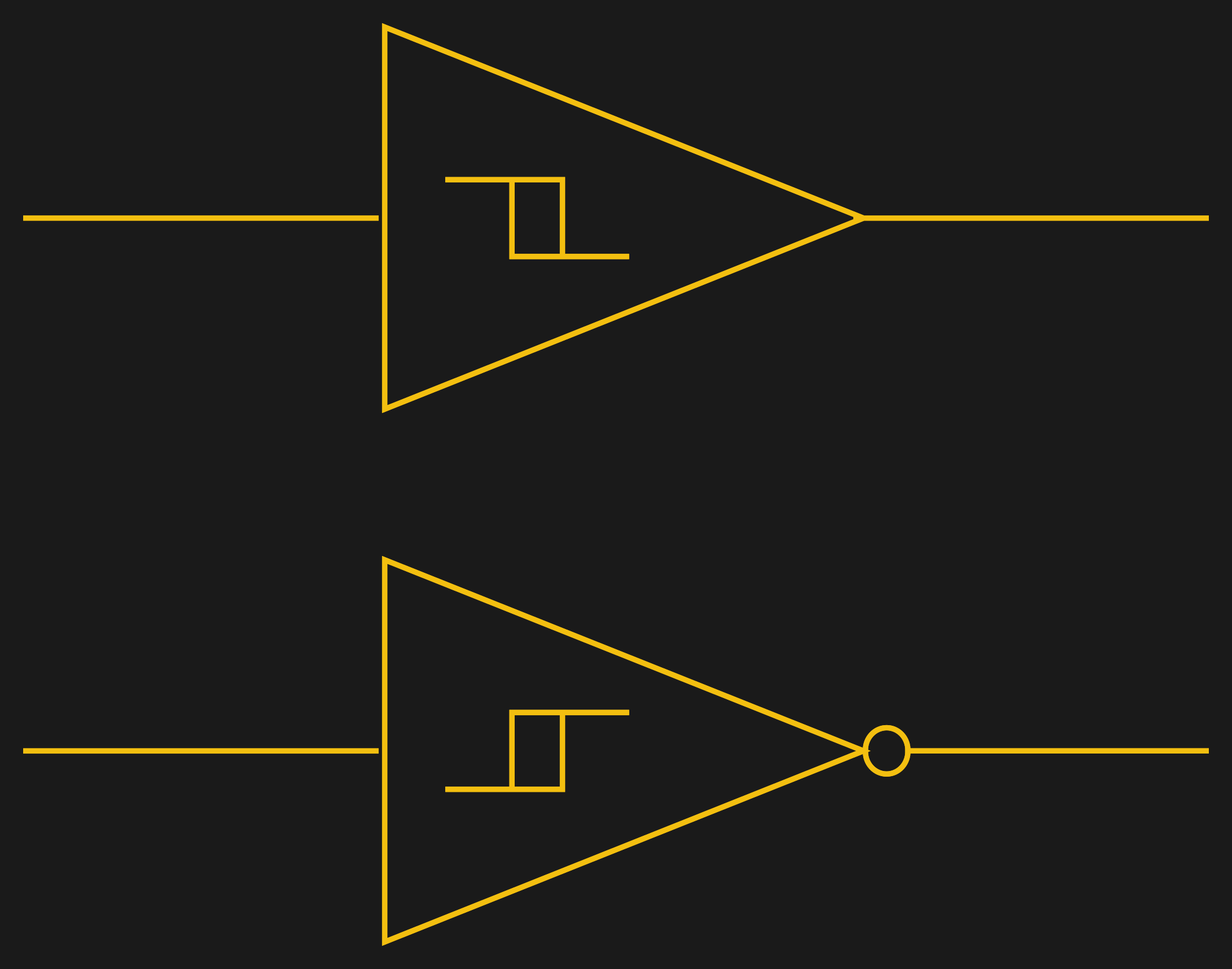
Assuming you want a Schmitt trigger in a circuit, you have plenty of options. There are ICs like the 74HC14 that include six (inverting) Schmitt triggers. On a schematic, each gate is represented by one of the symbols to the right; the little mark in the box is the hysteresis curve, and the little bubble on the output indicates logical negation when it’s an inverter.
You can also make them yourself out of transistors or even a 555 chip. But the easiest way by far is to introduce some feedback into a plain op amp comparator circuit.
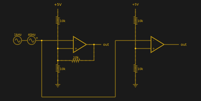
Below are two op amps, one with some positive feedback to make it act like a Schmitt trigger. The other is just a plain comparator. You can simulate the design online.
If you haven’t analyzed many op amp circuits, this is a good one to try. First, imagine an op amp has the following characteristics:
The inputs are totally open.
The output will do whatever it takes to make the inputs voltages the same, up to the power supply rails.
Neither of these are totally true (theory vs. practice, again), but they are close enough.
The comparator on the right doesn’t load the inputs at all, because the input pins are open circuit, and the output swings to either 0 V or 5 V to try, unsuccessfully, to make the inputs match. It can’t change the inputs because there is no feedback, but it does make a fine comparator. The voltage divider on the + pin provides a reference voltage. Anything under that voltage will swing the output one way. Over the voltage will swing it the other way. If the voltages are exactly the same? That’s one reason you need hysteresis.
The comparator’s voltage divider sets the + pin to 1/2 the supply voltage (2.5 V). Look at the Schmitt trigger (on top). If the output goes between 0 V and 5 V, then the voltage divider winds up with either the top or bottom resistor in parallel with the 10K feedback resistor. That is, the feedback resistor will either be connected to 5 V or ground.
Of course, two 10K resistors in parallel will effectively be 5K. So the voltage divider will be either 5000/15000 (1/3) or 10000/15000 (2/3) depending on the state of the output. Given the 5 V input to the divider, the threshold will be 5/3 V (1.67 V) or 10/3 V (3.33 V). You can, of course, alter the thresholds by changing the resistor values appropriately.
Practical Applications
Schmitt triggers are used in many applications where a noisy signal requires squaring up. Noisy sensors, like an IR sensor for example, can benefit from a Schmitt trigger. In addition, the defined output for all voltage ranges makes it handy when you are trying to “read” a capacitor being charged and discharged. You can use that principle to make a Schmitt trigger into an oscillator or use it to debounce switches.
If you want to see a practical project that uses a 555-based Schmitt, check out this light sensor. The Schmitt trigger is just one tool used to fight the imprecision of the real world and real components. Indeed, they’re nearly essential any time you want to directly convert an analog signal into a one-bit, on-off digital representation.
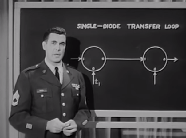
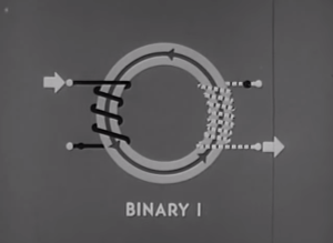
As the dashing officer shown above will tell you, early data processing machines and ADP systems employed two types of magnetic cores for memory and other purposes. This 1961 U.S. Army training film is an introduction to the properties of ferrite cores, which are commonly made from nickel alloy and other magnetic materials. As this is only part one of a series, the metallic ribbon type of magnetic core is covered in some other segment we have yet to locate.
The use of magnetic cores for random access memory was built upon transformer theory and provided a rugged and low-power solution until the semiconductor came into vogue. Before that time, the humble ferrite core served many uses and did so very well. The Apollo Guidance Computer had erasable magnetic core memory, and much of its software was stored in core rope memory.
The film covers a lot of theory and does so clearly and concisely. It begins by explaining what a magnetic core is and why it’s used, and then moves on to describe how the cores are used to store bits and the method by which they can transfer information to other cores. Along the way, it provides background on bi-stable devices and provides explanation of magnetization behavior in terms of magnetizing force and flux density.

 The film covers a lot of theory and does so clearly and concisely. It begins by explaining what a magnetic core is and why it’s used, and then moves on to describe how the cores are used to store bits and the method by which they can transfer information to other cores. Along the way, it provides background on bi-stable devices and provides explanation of magnetization behavior in terms of magnetizing force and flux density.


