Modern computers are so fast and complex that we would seldom try and fix them on a component level with simple DIY tools. Working on an early 1980s computer is much easier by comparison, with the fastest signals often in the single-MHz range. [Sayaka] demonstrates this by using a cheap $20 oscilloscope to troubleshoot and repair a Commodore 64.
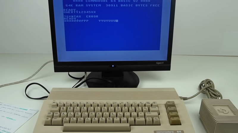
After powering it up for the first time, the C64 displays a BASIC prompt, but none of the keys seem to work. [Sayaka] did what good hackers do, and immediately disassembled it to try and figure out the problem, suspecting the CIA chip as a likely culprit.
[Sayaka] elected to purchase a cheap DS0138 oscilloscope kit to help troubleshoot the C64. It’s not the most capable thing, with a bandwidth of just 200 KHz, but it’s enough to do some work on an old retro machine. After probing around to check a number of signals, she noted that the CIA’s pins seemed to be very oxidized and suffering poor conductivity. All it took from there was a resolder job, and the computer was repaired.
We’ve seen other cheap scopes with altogether more impressive specs, too. Video after the break.


I bought one of these mostly for being an STM32 development board with LCD, and just for that it is worth it’s price. But I do not recommend this as a “scope”. The way the switches work is quite annoying to use, but worst of all are the software bugs and bad triggering. The scope is also very noisy. You can even see it on the low resolution LCD. Another issue is the very low quality of the switches. I had one failing switch, and at least one other that sometimes has intermittent contact. If you are into a gadget in this price range, I at least recommend the DSO150 (aka DSO Shell) which has a decent plastic housing and rotary button for the settings and has a much better user interface. Because it has the voltage frontend under software control, it is also a much more fun project for adding functionality such as auto ranging, or remote control to / from a PC.
Another reason I bought both of these gadgets is because the software is (unfortunately only) partially open.
The STM32 (or clone) has a 12bit ADC but even on the 7 or so bit height of the LCD you can see the noise. I still wonder why it performs so badly, but I have never really gotten around to it to seriously investigate what is going on. I guess these uC’s need a full GND plane to get more out of their ADC.
The Flea-scope (See Hackaday link) seems to have more capable ADC-s and (I think) it’s software is fully open, but at the moment it still completely lacks an analog front end.
Probably using the chip vcc for the voltage reference. You can throw 3 bits right out, and the rest is due to measuring a small signal without much amplification
“It’s not the most capable thing, with a bandwidth of just 200 KHz, but it’s enough to do some work on an old retro machine. ”
So it’s an audioscope?! ;)
I reviewed a DS)138 a few years ago. It couldn’t manage 200KHz even, it was 3db down at 40KHz. 10KHz square waves looked sorta OK, but much above that and they were very poorly displayed. Better than nothing, but I got a 10MHz Picoscope from Pico Technologies about 8 years ago for about $100. It might be more now, but it’ll still be a better ‘scope deal than a DSO138. I later got a 100MHz Picoscope and I’ve been very happy with it for years.
For about the same price, one can get a “LHT00SU1” which is a combination oscilloscope and logic analyzer supported by Sigrok. 12MSps on both analog and digital or 24MSps on digital only, with memory depth only limited by the connected PC.
Or for about the same pric an used CRT oscilloscope from USSR..
Where can I find a working CRT scope for $20-30 including shipping? The only ones I can find that cheap are listed as “parts only”.
I dunno why I twitched so much when I first saw this video come out.
Maybe it was promoting those junky scopes, but if you have no scope I guess its better than nothing? But really save up a tiny bit more and there’s better options under the 100$ mark
Maybe its the title “I used a tool made to troubleshoot signals to troubleshoot signals” in combination with that kind of smug thumbnail (reminds me of talking to my 3 year old “yes honey, its a red car”)
Or maybe its a bit of both
+1
Do you have copyright on the “yes honey, its a red car” comment ? So made me smile… 32768,58 32769,41
no complaints from me, but I can not be the one that originated it
Adrian Black did something like this on youtube nearly a year ago. So much for being current.
I’m not entirely convinced that a factory soldered joint would get oxidized and make a bad connection. But I suppose it’s possible that it wasn’t a factory soldered joint. Or it’s also possible that this is one of those cases where things just start to work once you fiddle with it enough. We can’t say for sure.
I have noticed this in recent weeks/months maybe years where old gear gets taken apart and the no clean flux from the wave solder gets mistaken for “corrosion” or “oxidation” and so the person cleans it (no issues there I usually do too cause it looks like crap) then adds a bit of solder and like magic “problem solved”
Realistically its just a broken or cracked joint, it happens after decades of power / heat cycling in a random environment no matter how much brown snot is around it, you can ignore it, its not the root cause, its been there since day zero
Maybe reseating the keyboard connector fixed the non-responsive keyboard.
How does this mean they fixed it with a cheap oscilloscope? They found bad connections and fixed them, it’s not like they probed a clock and found it was the wrong frequency or anything, they just found bad connections.