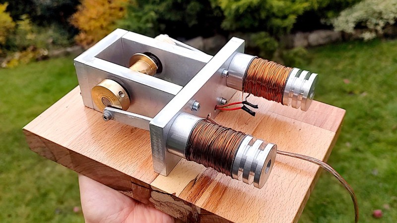
The reciprocating engine has been all the rage for at least three centuries. The first widely adopted engine of this type was the steam engine with a piston translating linear motion into rotational motion, but the much more common version today is found in the internal combustion engine. Heat engines aren’t the only ways of performing this translation, though. While there are few practical reasons for building them, solenoid engines can still do this job as well and, like this design from [Maciej Nowak Projects], are worth building just for the aesthetics alone.
The solenoid engine is built almost completely from metal stock shaped in a machine shop, including the solenoids themselves. The build starts by making them out of aluminum rod and then winding them with the help of a drill. The next step is making the frame to hold the solenoids and the bearings for the crankshaft. To handle engine timing a custom brass shutter mechanism was made to allow a set of infrared emitter/detector pairs to send signals that control each of the solenoids. With this in place on the crankshaft and the connecting rods attached the engine is ready to run.
Even though this solenoid engine is more of a project made for its own sake, solenoid engines are quite capable of doing useful work like this engine fitted into a small car. We’ve seen some other impressive solenoid engine builds as well like this V8 from [Emiel] that was the final iteration of a series of builds from him that progressively added more solenoid pistons to an original design.


(1) The pistons should be 90 degrees apart, not 180. Then it won’t “get stuck” with both pistons topped / bottomed. (2) Add a neodymium magnet to the end of a bass piston, then you can implement Piston 1 – push; Piston 2 – push; Piston 3 – pull; Piston 4 – pull.
The pistons can be any orientation, what counts is the cam position. It´s the cam that determines the position of the pistons.
If you let your mind wander a bit, you’ll see that this becomes a strange 4 steps-per-turn bi-polar stepper motor.
tis such a pretty build
shame he couldn’t find a way to wind the coils better
Wind. The. Could. In. A. Lathe. In
Threading. Mode.
The. Carriage. Travel. Could. Be. Selected. By
The. Wire. Diameter. Example. 062. Dia. Wire
Same. As. 16. Treads. To. Inch. . right???
This is a charming motor, though the “cylinder” design strikes me as inherently flawed.
Because the coils in the engine are rapidly turned on and off, their magnetic field is in nearly constant change. By fabricating the bobbins of aluminum, you in effect create a transformer, where the switched coil is the primary winding and the body of the bobbin (being conductive) is a massive shorted turn.
The effect is to waste a lot of energy (you may even experience heating in the bobbin). In any event, this may explain the comparatively anemic response of this motor to a robust 16-volt power supply.
The fix is to remake the “cylinders” out of something non-metallic. Phenolic and many plastics will machine nicely. This is also a part that could easily be 3d printed.
If you insist on a metal bore for the “cylinder” (to provide a nice sliding surface for the piston) this can be introduced as a length of brass or aluminum tubing, PROVIDED that said tubing is slotted with a mill or slitting saw along its entire length. The slot neutralizes the “shorted turn” behavior that an otherwise solid tube would exhibit.
One other thing… I would like to have seen a schematic or parts list for the switching circuit. The populated board is visible for a few frames in the video, but it’s difficult to see exactly how it’s set up. I do note the apparent absence of “flywheel” or “kickback” diodes.
When you energize a coil and then abruptly interrupt the flow of current, the collapse of the magnetic field can induce very large voltages in the coil terminals–large enough to damage and destroy your switching transistors over time. Unless flywheel diodes are build-in to the transistors themselves (in some cases they are) the diodes need to be added externally.
All that said, very nice project and very nice motor.
All valid points, and quite a long list of fundamental flaws.
That’s only part of the story. Many solenoids and relays use a shorted winding of some kind to reduce kickback energy and control timing, it’s often just a thin metal tube inside the bobbin bore. So the full-metal bobbins are not completely flawed, but their electrical characteristics might be severely wrong.
This design its just for fun, not for use. As a Marine Engineer, i do not see any reason to waste electric power on solenoid coils to obtain rotational movement with a lot of friction instead to use it on a normal electric motor, where the electromagnetic field its transformed in rotational movement with less friction. Just a toy for children.
Couldn’t the Solinoid (Alternatly Push-Pull) Like the old steam engines worked (each stroke had power) power pulling up, power pushing down on each rod stroke.
And what is it that keeps it from spinning backwards?
Could you please stop featuring those projects, where someone pretends we live in the 16th century, and he invented something awesome, whilst ignoring the most basic state of art? Ist like building an electric circuit whit wet wood instead of wires, and running it with high voltage to get at least some effect, instead of using proper conductors (copper in the case of electrical current, iron in the case of magnetic flux). I feel every of those videos reduces mankind’s collective knowledge.
+1