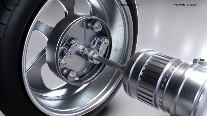
Power delivery in passenger vehicle drivetrains hasn’t changed much since the introduction of the constant velocity (CV) joint in the 1930s. Most electric vehicles still deliver power via the same system used by internal combustion cars. Hyundai/Kia has now revealed a system they think will provide a new paradigm with their Universal Wheel Drive System (Uni Wheel). [via Electrek]
What appears at first to be a hub motor is in fact a geared wheel that keeps the motor close without the problem of high unsprung weight. Power is fed into a sun gear which can move independently of the wheel allowing the system to maintain a more consistent driveline and avoid power variability over the range of suspension travel like you’d find in a CV joint experiencing high deflection.
We have some concerns about the durability of such a system when compared with the KISS and long development history of CV joints, but we can’t deny that moving the motors of an electric vehicle out to the corners would allow more packaging flexibility for the cargo and passenger areas. We’re also excited to see open source replicas make their way into smaller robotics projects now that the images have been released. If you’ve already made one in CAD, send us a tip at tips@hackaday.com.
Looking for more interesting innovations in electric cars? How about an off-grid camper van? If you think automakers are overcomplicating something that should be simple, read the Minimal Motoring Manifesto.


Where’s the young Instagram/TikTok boy that yells, “bullsh*t”.
bullsh*t :D
Hate to break it to them but most of those benefits are easily achieved by making the bearing larger and putting the current CV axle inside it. Also the standard motor could allow the drive axle to go alongside it, barely taking up any more room than the design they showed. The current (pun intended) motors are not taking up very much space at all. Especially when you consider the trend is still SUV shaped tall vehicles.
Looking at the video I’m also not sure how it makes a turn with the front wheels.
Watching this makes me think why cars are the way they are. VW for example will take “test mules” fitted with a prototype if an upcoming drivetrain and flog them for 1000s of KM/miles and when a part breaks they redesign it. An example being the size of the Rzeppa joints being 90mm in the early 80s, then 100mm, then 110mm, then plunging tripod style inner joints.
I’m glad they are throwing stuff at the wall, and I’d be glad to have their drive system in a free tractor, one that I didn’t need to do any work with. If they need to ‘innovate’ to find the optimal final drive ratio, I smell vaporware. (There are many free caclulators for such information, and we would need an application: EG 4,000 lb car driving up Lombard in San Francisco at 10mph with motor torque of 200 lb-ft)
That said, it does seem well suited to small slow moving autonomous vehicles
Agreed, I can’t picture the “sun gear” being at any position other than 12 o’clock once they add a several thousand pound car on it.
You are not just transfering all of the torque from the motors thru the little bearings on the gears you are carrying all of the weight of the vehicle divided between all of those gears and pivots. Also the motion of that wheel is no just going to go up and down but forward and back under acceleration and braking in a steering axle that front and back motion is going to make it a handful at higher speed.
I assumed they did not show the suspension in the video and it would be using standard multi-link setup. I am very confused and would be amazed if this was actually viable for general purpose Automotive use.
With multilinks, double wishbones or struts the wheels also move in and out from the centreline of the vehicle. Struts and multilinks change the camber angle as they move up and down. All three suspension options would be out. I think this would require a trailing arm (or leading arm?) suspension to keep the wheel vertical and moving in one plane.
While its not going to cope with angles as extreme as a CV joint pair can I suspect this would have rather more wiggle permittable than you suggest – all those gears must have a little clearance in them which will let it be canted out of plane somewhat. Clearly not going to work for your extreme suspension travel rock crawler where there is so much travel in all directions required, but probably fine for your normal road car (not that I think it is likely to replace CV any time soon, seems like it doesn’t solve any real problem worth solving while adding many more challenges).
I thought a “CV joint” was a “constant velocity joint” in this context. The other, seemingly unrelated use of “CV” is “continuously variable transmission.
Totally right there. I should have it fixed in a sec.
I get the idea here… but wouldn’t that unit need to be sealed somehow? Yet somehow with a long slot for a rotating axle to slide up and down? If it were not sealed a bit of road dust would turn all those lovely gears into expensive metallic dust in short order.
Also, one of the things the video so happily shows being got rid of is the brake disk and caliper… are they planning on making that all electronic with the motor? Through though little gears?
Wasn’t this just posted to Hackaday a few days ago?
No, you were probably confused, just like me, by the slashdot article a few days ago…
https://tech.slashdot.org/story/23/12/01/0032246/hyundai-and-kias-new-uni-wheel-drive-system-could-revolutionize-ev-design
People still read that cesspool of a site? It used to be good mid 2000s, in the last 10 years it’s become a hive of trolls and really unpleasant things trying to approximate humanity. A lot of toxic hive minds, and people convinced they are smarter than 99.999% of the human population. The rest are edgelords.
Its a shame, it really used to be a useful place.
If we could get our hands on enough slashdots, we could make a Beowolf cluster of them!
I think they missed one logical step in between
1. just shortening the middle part of double CV joint arrangement and
2. developing this Uni Wheel.
namely removing just one of the CV joints, attaching the electric motors there and mounting them pivot-able(? dunno the right term).
-> more space + motor weight still “fixed” in the car / not inside the wheel.
I think the space savings would be similar (but I’m probably missing some cons).
Interesting, might work actually. Except for copper wire fatigue, might be an issue.
Had that thought some time after writing my original comment too – if only there was an edit option I’d have added it.
But I have no idea which pros would outweigh which pros or not…
I think that the problem is that for a cardan joint to be “continuous velocity”, you must have two that move in opposite directions. If you only have one, the radial speed isn’t constant. There was a video about that in youtube…
(with “move in opposite directions” I mean “flex in opposite directions”. Sorry)
True for cardan joints but as I understand it there are several without this “flaw”:
https://en.wikipedia.org/wiki/Constant-velocity_joint?useskin=vector
A CV joint will still be needed since the wheel might get out of alignment with the motor after driving X kms.
How do you mean? The wheel would move forwards or backwards?
One potential issue that jumps out at me is the number of tiny little gears spinning at EV motor speeds, a typical EV diff only has one part doing those kinds of RPMs. There could be heat and/or wear issues with those especially because they’re so small.
It seems that this suspension requires a linear travel in the suspension. It’s basically a Morgan sliding pillar suspension from the 1930s. There is no ability for passive changes in camber or caster under load.
Lots of small cogwheels are not good for efficiency. 92% (as shown in the video) is a concern. That’s a lot of heat that needs to be transferred to somewhere else.
The inside of the wheel is a pretty hostile environment. Water, dust, salt and the heat from the brakes when braking. I doubt it would last more than 10000 km (7000 miles).
But it’s a neat concept. Maybe first for slow moving vehicles.
Put the motor in the wheel. Basta.
That’s unsprung weight, which as the article says, we’re trying to avoid.
Avoid, but not at all costs.
Ever added up the weight of tires, rims, and brake parts for a modern vehicle? It’s pretty significant, but we aren’t trying to switch to inboard brakes and bike wheels or go back to smaller sized wheels despite the weight penalty. Sometimes you even see solid axles, though not much in cars anymore. We consider those sorts of thing worth having despite the tradeoffs, but in an alternate universe maybe they have hub motors and inboard brakes for some reason, and someone’s had a similar idea about the whole thing.
Having outboard brakes means that the suspension has to not only support the car but hold the brakes against the large torque they produce. You can brake much harder than you can accelerate in normal cars, as brakes are so strong. However, suspension parts can be somewhere in between sprung and unsprung, so extra weight (if any) only partially counts.
Another similarity with brakes is that they have to be protected against the same grime as a motor would, and need brake lines run much like the electric lines for a hub motor. If you have large, high quality discs all around and you get a deep scratch from a small pebble or something, you’re looking at a pretty annoying repair bill. You have to have a gap for the travel of the system, and you have to have a high clamping force, and you have to have an easy path for airflow to dissipate the heat since they’re not liquid cooled or anything. Even though there’s no electrical windings or contacts involved, it’s still vulnerable if you happen to get unlucky with mud like I did. I wouldn’t be surprised if a well-sealed hub motor had much less trouble than brakes do, even though it’s not as simple in concept.
I’m not saying hub motors are better, just that it’s not obviously stupid.
And yet for some reason we do add disc brakes to the wheel (when they could also be added to the axle). And a disc brake weighs ~20lbs, just like 1/4th of a tesla motor (70lbs).
So yeah. Put the motor in the wheel. Basta.
(disc brake weight: https://trade.mechanic.com.au/news/brake-discs-is-lighter-actually-better)
(tesla motor weight: https://www.reddit.com/r/teslamotors/comments/7g09cu/its_pretty_easy_to_find_the_motor_weight_for_the/)
As long as the hub motors can normally handle the braking, I wouldn’t mind if the regular brakes were lighter and weaker to compensate, especially on the rear. I used to drive something where the fade was significant enough and the total braking poor enough that one quick stop from 75mph would make a huge difference in the next application. With engine braking and taking care to manage fade, it was acceptable at the time, and with modern regen of sufficient force, it could even be a non-issue especially if the problem was managing fade rather than total braking force.
It might also work to have full brakes and of course steering on the front but not motors, and two larger hub motors on the rear with more minimal brakes. Maybe drums would save weight. They lend themself to high initial force with worse fade. (Just an off the cuff idea, based on figuring that keeping the front planted and reliably braked is more important)
I find it weird that Hyundai has made a big press release and swanky video about something almost the entire engineering department must’ve facepalmed over when they saw it.
It’s an interesting mechanism but it creates as many problems as it solves and I’m very sceptical it’s more efficient than a CV joint – sure CV’s get less efficient as you turn harder but then you’re not cruising along for miles on full steering lock…
Honestly feels like someone’s uni project that the marketing department got hold of and decided to shout about without asking if it was in any way sensible.
Well.. given this company has troubles keeping engines running much past their warranty period (if you’re even that lucky) this is no big surprise to anyone.
I never used tiktok but i have to yell BS at this one.
Anyone with even a small familiarity with automotive suspensions will know that.
This looks like it belongs on a slow moving NASA rover far more than it does on a road car.
Looks great!
If the point is to engineer a throwaway car that will only just outlive it’s warranty in order to keep consumers buying more.
“We have some concerns about the durability of such a system when compared with the KISS”
Wow. That seems like quite the understatement!
I have a sketchbook somewhere from the 90s where I drew something like this. Though I was trying to design a transmission that would fit in the wheel hub instead of an alternative to the CV joint. Now I remember why I never took it past the sketches.
This looks like it would be better suited to robotic flatbed haulers for unimproved/gravel surface freight yards. Something that can crawl into and out of aircraft, scoot around cargo container ports and rail depots without needing pavement. A beefier version might be useful in light to medium duty agricultural applications where torque is more important than speed.
If they oriented the motor so it was 90 degrees to the drive shaft (yes, I know one more gear means more friction) then the motor could be mounted vertically to be inline with the suspension pistons. If sold as a single assembly in that configuration, they could be used as modular drive units similar to the ones on 500 ton payload hydraulic modular trailer (HMT) platforms; the massive flatbeds with 200 wheels that “drive” in any direction.
As other commenters have pointed out, the wheel hub on a vehicle moving at highway speeds is a hostile and violent environment. Ice, heat, road gravy, dust of all kinds, broken down petroleum products of all kinds, organics, rocks and debris, potholes, flash cooling from rain and puddles, impacts at speed, and finally constant intense vibrations. This configuration is going to need to be torture tested and then some.
what ever happened to in-hub motors?
too much unsprung weight I think.
Could have uses in PEVs (personal electric vehicles). I was sniffing around it for such a project but whoever said above that it creates as many problems as it solves might be right.
Concept vehicle in the video has about half an inch of wheel travel possible. Even real vehicles rarely have more than 75mm of “normal use” bump/droop in operation, except on large potholes. In what world do CVs have sufficient driveline speed/torque variation with a 5 degree deflection in any situation that requires perfectly constant power transfer? None. Solution looking for a problem.
I don’t get the automobile’s industries desire to get rid of KISS. They are making everything extremely complicated for seemingly minor benefits. So they are going to replace a reliable $100 axle with a complicated, likely $1000 assembly to save a couple of FT^3 in an inaccessible area of the vehicle??
In the video the max speed tested is listed as 120 Km/h (about 74.5 in miles per hour).
That is slower than all Teslas max speed right?
But that’s not all, the video completely ignores that those gears obviously have to be in a bath of oil I would think, and with a max speed of 120 I guess that they are at max temperature during normal highway driving (in the EU various places have a max speed of 120 on the highway) and that oil would need to be circulated and cooled right? They just leave all of that out of their presentation.
As for that oil and its circulation, it is in the wheel and experiences centrifugal forces that push it outwards, and I wonder if that is an issue too, or maybe an easy way to circulate it? But then I wonder also how heavy the wheel becomes and how all that stuff affects braking, if at all.
Now I have no idea how that compares with exisiting systems, and what solutions have been invented already for the mentioned issues, you tell me.
Correction: I don’t know where my mind went but obviously that centrifugal stuff is nonsense since the gear part does not rotate and it’s only an outer rim with tire that does.
Still leaves the oil question and all that though.
Glad nobody/few read my comments because I was being real stupid with that centrifugal forces bit.
Another new addition is that I now think that oil cooling is extra important to keep the rim part temperature in control.
Intern project. Not important that it can’t steer, among other things…