We all know that solderless breadboards have their limitations. All that stray capacitance can play hell with circuits, especially high-speed stuff, but they’re so darn useful that avoiding them in favor of some other prototyping method can be really hard. So we often just forge ahead, plugging in our parts and hoping for the best
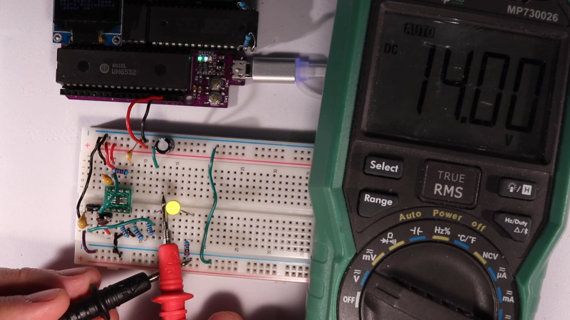
A recent veteran of the breadboard battle is [Anders Nielsen], who kicked off a new project by prototyping this high-voltage boost converter on a breadboard, with mixed results. The project is a scratch-built programmer for old-school ROM chips, a task normally farmed out to a dedicated programmer, but where’s the sport in that? Besides, this is the future, and generating the 12 to 14 volts needed should be a snap. And it would be, except for the fact that his chosen chip, a MIC2288 switching boost regulator, is only available in an SMD package. Getting the chip and a few other SMD support components onto breadboard-compatible breakouts proved to be challenging, and getting it working once it was there was even more work.
A lot of the trouble was down to simple breadboarding errors, but the big problem was the input capacitance, which [Anders] had to fiddle with quite a bit to get the converter to 14 volts. The current maxes out at about 25 mA before the voltage starts dropping, which just might be enough to burn those old chips, so we’ll call this a provisional win and see what happens when he builds the rest of the programmer.
[Anders]’ experience here raises a good question: what’s the best way to prototype using fussy SMD components? PCBs are cheap enough that it’s tempting to go straight to one, but swapping parts in and out like he had to do here to get everything just right would be much harder that way. We’re not sure we know the answer, but we’re pretty sure we’ll hear your thoughts on that in the comments section.


With switching circuirs, excessive wire inductance is as much of a problem as capacitance. A rule of thumb is 1nH/mm, so a 4 inch/100mm wire “contains” 100nH. Use that to work out resonant frequencies and induced voltages when circuits switch. Start with i=C*dV/dt, and v=L*di/dt.
To avoid problems with solderless breadboards, use the appropriate combination of techniques including SMD carriers, Manhattan, rats nest, all built on a PCB containing a ground plane.
Yes, that requires quick and dirty soldering, but it can be fast and reliable/permanent and have good performance characteristics.
Or you can spend more time debugging the solderless breadboard than debugging your circuit. The choice is yours :)
Even more specifically — because switching converters are almost always below Zo (transmission line impedance of the wires / structures involved), inductance is dominant; there’s capacitance sure, but it’s not nearly as big a deal as the inductance is. (The converse is true for hi-Z circuits, which includes some analog circuits still, but also essentially everything in the vacuum tube era for example.)
The easiest way to prototype with SMD components is to use carrier PCBs.. SurfBoards used to be a commercial option, but I have a dozen or so I’ve designed for myself and sent to a board house for fabrication.
Without those, it isn’t all that hard to dead-bug on copper clad or perfboard as long as you’re staying in the SOIC (0.050″ pitch) family. TSSOP (0.025″ pitch) is doable, but takes a bit more effort.
The biggest trick is to use fine enough wire. 30-gauge is stiff enough to rip the pins off an SOIC package. 34-gauge to 36-gauge magnet wire is a good choice: it’s light enough to be flexible compared to a chip’s pins. The current limit for runs more than a couple centimeters is about 100mA, but you can accomplish a lot running jumpers a few millimeters from a chip’s pin to something more solid: holes in perfboard, isolated chunks of copper clad, or even pieces of heavier wire glued down so they stay put.
Now I remember i once did a vaycay house programming session with dip-switches for address and data on some smaller 16×4 proms, a 555 timer would generate the 50 mS or so pgm pulse and I’d loot the house for batteries soldered in series for the programming voltage. I even called a support number on the pay phone for some question in the data sheet, feeding coins into the slot like mad since this was long distance in those days. What a nerve-wrecking adventure. I even got a loose end on one of the wires from the dip but I managed to do a second round since you could always program new zeroes but once a zero was burned in the wrong place you where screwed. Lucky for me it was a data wire that’d come loose. Now you know.
Sounds like a lot of fun. I prefer OTA updates.
external pass element switchers are a challenge to get right even with a PCB sometimes. Parasitics matter. Having a proper ground plane matters…none of which is provided or easily understood on a breadboard. Even if you do manage to get a design working, odds are you end up repeating the exercise when you move to a PCB because you probably have no idea what you really did to get it to work.
I always carefully read the apps section of the part datasheet for layout concerns, followed by finding the eval kit for the part and studying how they did the layout. With that its usually straightforward to get it working the first time.
PCBs are cheap and easy to get these days, I just don’t get why people don’t prototype directly on a pcb, or as others suggest, do a dead bug on some copperclad. breadboards are the wrong tool for this.
A dirty old MC34063 would have done great here. Fast transient response and it doesn’t hardly care about layout.
Or hey even just a 555 and some caps for a voltage tripler.
Today my curiosity got the better of me, so I put the inductor and 10uF input cap straight across the pins on the breakout – then I replaced the top FB resistor with a 100k pot..
Result: Rock solid performance from 4-27V with a 90mA load.
I suspect I was dealing with quite a bit of stray breadboard inductance.
When the app notes say “as close as possible” it helps to listen :)
Anecdote:
A coworker was having power-up issues. Their board was supposed to be rated 40V, but was failing on raising the input to 27V or so, particularly under load. Hmm. Inspected the board a bit, nearest bypass cap was 5cm or so away. Did some rough figures. Regulator probably has 10ns edges, 2A peak; 50nH*2A/10ns = 10V, plausibly overvolting and popping the regulator. I told them, put a 1uF right on top of the part, using very short jumper wires if necessary. Worked fine up to nominal voltage.
For breakout boards, it’s good to put local bypasses, or whatever other switching-related stuff (for buck/boost regs, the catch diode if applicable) on the board. When I’m doing an experiment with a new power circuit, I put the critical stuff on copper-clad (scratching traces/pads in, or soldering pads on top Manhattan-style), and the low-level signals I run wires or headers to the solderless breadboard.
Breadboarded a 130 khz resonant tank circuit, had no idea what voltages I’ll be working with. Feeding 12v square ended up with 400vdc+ once rectified into 220 pF. Getting shocked was my first clue
The easiest way is to not do it at all! There is value in the old controllers and regulators like UC3843, or, god forbid, MC34063 even (but there’s a much improved NCV3063 variant if you essentially need one, but actually good), which aren’t fast enough to be so strict with layout. I’ve even knocked out a discrete regulator here or there, not something I’d really suggest making a habit of, but it can be done.
Test
You can always just buy small adjustable dc-dc converters, adjustable too with a small trimmer pot
Simple as input voltage to pair of pins, you use trimmer to set output voltage
Much Easier to use a header that saves pcb space unless you making a psu, usually if you need a -12 or -14 or -5, although that’s also just reversing your + and – backwards