In the realm of amateur astronomy, enthusiasts find themselves navigating a cosmos in perpetual motion. Planets revolve around stars, which, in turn, orbit within galaxies. But the axial rotation of the Earth and the fact that its axis is tilted is the thing that tends to get in the way of viewing celestial bodies for any appreciable amount of time.
Amateur astronomy is filled with solutions to problems like these that don’t cost an arm and a leg, though, like this 3D printed equatorial table built by [aeropic]. An equatorial table is a device used to compensate for the Earth’s rotation, enabling telescopes to track celestial objects accurately. It aligns with the Earth’s axis, allowing the telescope to follow the apparent motion of stars and planets across the night sky.
 Equatorial tables are specific to a location on the Earth, though, so [aeropic] designed this one to be usable for anyone between around 30° and 50° latitude. An OpenSCAD script generates the parts that are latitude-specific, which can then be 3D printed.
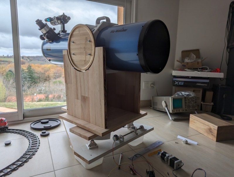
From there, the table is assembled, mounted on ball bearings, and powered by a small stepper motor controlled by an ESP32. The microcontroller allows a telescope, in this case a Newtonian SkyWatcher telescope, to track objects in the sky over long periods of time without any expensive commercially-available mounting systems.
Equatorial tables like these are indispensable for a number of reasons, such as long-exposure astrophotography, time lapse imaging, gathering a large amount of observational detail for scientific purposes, or simply as an educational tool to allow more viewing of objects in the sky and less fussing with the telescope. They’re also comparatively low-cost which is a major key in a hobby whose costs can get high quickly, but not even the telescope needs to be that expensive. A Dobsonian telescope can be put together fairly quickly sometimes using off-the-shelf parts from IKEA.


And I was just starting to look at putting one of these together. :D Perfect timing.
Should you want to build one, all details are here: https://www.thingiverse.com/thing:6362263
Plese don’t hezitate to ask for explanations if needed.
I think you’re using a script to generate models, will it allow users to go above 50degrees latitude?
there is no lock in the script. The higher the latitude the more vertical the axis will be (short distance between VNS and south ball joint… Unless you’re at the North pole, it should work… Try the script and see what it says
I was really just wondering whether it did cater for higher latitudes and it does :-)
If I was going to build (rebuild in my case) something like this for an alt/az mount I would probably build a wedge, especially if it was for a motorised alt/az mount, on mine it has an EQ mode and the wedge turns it into an EQ tracking system.
Follow the links to his channel. Pretty impressive shots of the moon. Or please add to the article.
Overview of the equatorial table:
https://www.youtube.com/watch?v=ka9uXJvbwiM
And the moon (and Jupiter) video:
https://www.youtube.com/watch?v=I6fJBA_TYC4
I am impressed enough that I might build one.
cool ! thanks
Looking closely at the picture – big telescope project, stepper motors, a CRT o-scope, nice view out the window and a model train with seemingly no furniture to be found. This person is immediately likable and has their priorities in line!
Not just ANY model train, a LEGO model train!
Exact !
LOL!
I will not show this comment to my wife :-)
Having to print parts specific to your latitude seems wrong. Surely the trick is to use 2 stepper motors with low-backlash printed reduction gearboxes, then you can just plug your latitude in at run time and the steppers will both move so as to make a telescope mounted on a “battleship turret” (yaw and pitch) stand track a point in the sky as the earth moves. It would be bothersome to have to reprint parts if you move house in a north-south direction. This would also, providing each axis has sufficient travel before hitting a physical limit, let you run from anywhere on earth, not just the 30 to 50 degree latitudes.
You have described an altitude-azimuth mount. Common as dirt for cheap telescopes, and famously deficient in that the image in the eyepiece (or focal plane) rotates as the mount tracks, ruining long exposures.
Not to be a D but equatorial mounts align one axis with earths rotational axis to simplify star tracking. This seems to be a guided motorized mount. No need for equatorial alignment in that case. Cool project none the less..
https://en.wikipedia.org/wiki/Equatorial_mount
It is an equatorial table (not mount) which rotates around a virtual North South axis. You then have to align it with the North South direction to make it compensate Earth rotation.
It’s totally overengineered but how exciting it would be to misuse all that excessive engineering for mounting an SLR and shooting pics of the sky.
It will work for sure… And you’ll see how existing it is to lock your first star in the middle of the viewfinder !
Thanks bro, you did a great job!
I’ll try to replicate it to use as an overengineered barn door tracker. I need to find a way to align with the celestial south pole down here in the southern hemisphere, since Polaris isn’t available for us. Maybe I can use the Southern Cross or Sigma Octantis for rough polar alignment before fine tuning.
Or… maybe a gyroscope, accelerometer and GPS module should give me the data to accurately calculate the south pole position and make a completly non sense and very funny overkill machine.
Hopefully I can get this beast done and properly aligned for some sweet astrophotography soon enough!
why not using a simple compass ? Or, best, if you stay at home, just check the direction of shadow of a vertical wall at noon solar time. Mark it and align on this line…
And where’s the fun in making it so simple ? :-)
I’m shocked that I’ve been casually using equatorial and alt-az mounts for a half century (but never a Dob), and I have never heard of the equatorial table.
Fascinating design. The math is a little too hairy for me to just scribble down on a napkin though. Trust a Frenchman to have gotten it right.
It has been invented by a Frenchman in 1970 or so Mr Poncet… So you can trust :-)
(link in french https://fr.wikipedia.org/wiki/Table_de_Poncet)
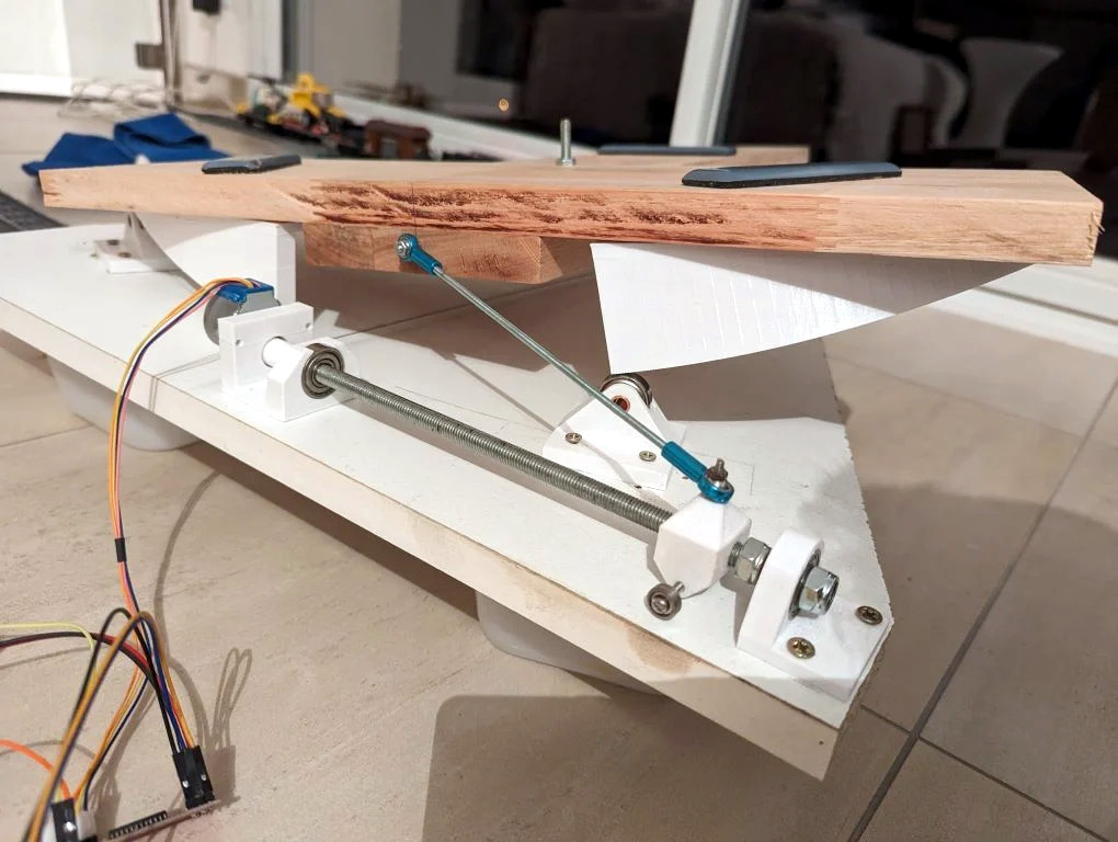
I changed the drive system of my 3D printed equatorial table.
Previous concept was with a lead screw, it had some drawbacks mainly backlash and software complexity.
This new concept uses:
– a planetary geared stepper motor (1:51) which provides plenty of torque
– a wire
– a spring
– a cylindrical North sector only used to guide the wire
Pros of this option are:
– a much more stable platform with no backlash. There is a very minor springy effect due to the wire and the spring, but this is not visible during imagery
– return to home is much faster
– observation can be started whatever the initial table position as the motion is fully linear
– firmware is greatly simplified !
Here is it performing a return to home
https://www.youtube….h?v=mnKlnrRpf_w
sorry bad link
https://www.youtube.com/watch?v=mnKlnrRpf_w