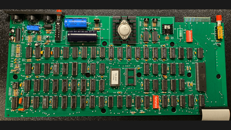
If like us, you missed out on the TRS-80 Model I back when it first came out, relax .With this brand-new PCB that’s a trace-for-trace replica of the original and a bunch of vintage parts, you can build your own from scratch.
Now, obviously, there are easier ways to enjoy the retro goodness that is the 46-year-old machine that in many ways brought the 8-bit hobby computing revolution to the general public’s attention. Sadly, though, original TRS-80s are getting hard to come by, and those that are in decent enough shape to do anything interesting are commanding top dollar. [RetroStack]’s obvious labor of love project provides the foundation upon which to build a brand new TRS-80 as close as possible to the original.
The PCB is revision G and recreates the original in every detail — component layout, connectors, silkscreen, and even trace routing. [RetroStack] even replicated obvious mistakes in the original board, like through-holes that were originally used to fixture the boards for stuffing, and some weird unused vias. There are even wrong components, or at least ones that appear on production assemblies that don’t show up in the schematics. And if you’re going to go through with a build, you’ll want to check out the collection of 3D printable parts that are otherwise unobtainium, such as the bracket for rear panel connectors and miscellaneous keyboard parts.
While we love the devotion to accuracy that [RetroStack] shows with this project, we know that not everyone is of a similar bent. Luckily there are emulators and clones you can build instead. And if you’re wondering why anyone would devote so much effort to half-century-old technology — well, when you know, you know.
Thanks to [Stephen Walters] for the tip.
Feature image: Dave Jones, CC BY-SA 4.0, via Wikimedia Commons


This is awesome! 😃👍
But I have one question – why? 🤔
I mean, the shell, the keyboard, the monitor etc are all pretty nice and functional, but..
The computer itself wasn’t so, um, great.
So I’ve expected an improved version, rather. Say, with an integrated graphics board or something else mentioned here: http://www.trs-80.org/model-1/
probably the one they had growing up or something like that.
I understand, but if I was going to recreate my favorite system, I would integrated something like a programmable character generator.
In my case, there really was an official upgrade of that sort available back in the 80s. It replaced the original character ROM with an external character RAM (+ logic for reprogramming it; PCG700).
The TRS-80 had something similar in the form of the 80-GRAFIX, I believe.
I had one of these “Treasure 80s” just after college. There was a simple character ROM replacement that provided for lowercase characters with descenders (I don’t recall if there were any trace changes). That was a must-have when using software such as Scripsit (the word processor of the day).
I simply gave away the model 1, monitor, expansion interface, serial card and floppy drives after holding onto it for years.
Ah, the old TRS-80 Mod I.
The minute the warranty ran out I had the screws backed out of the case.
My TRS80 did not require a change of character ROM, lowercase was already part of the chip’s capability. It did, however, require the addition of a static ram chip to add another bit to the screen memory. If memory serves me, I piggy-backed the additional chip on top of an existing ram chip and soldered all the legs except for the data and select lines. Fly wires took those signals where they needed to go.
I also added reverse video and a numeric keyboard (made from keys salvaged from another computer). Later, I added a built-in Votrax SC-01 for speech.
I eventually gave away my system, too–computer, monitor, expansion chassis, two floppy drives, and modem. There are times I miss that machine.
I don’t know much at all about computers but I do know that I have a box with brand new parts and several circuit boards for the TRS-80 11 ( the 2nd one ). If anyone is interested in them.
I know this is an old comment but I’m trying to fix mine. I’m AnotherMaker on YouTube and my contact email is in my channel “about” section if you’re still interested. Just click the “more” on my channel page.
The PCB is only a part of what’s going on. The rest of it is here:
https://github.com/RetroStack/TRS-80-Model-I
“RetroStack is passionate about exploring and preserving the legacy of older computer systems. My work involves creating detailed documentation and videos to share the knowledge. I am also dedicated to reviving these classic systems by reimplementing them and offering replacement parts at no cost.”
Thank you for the information.
The other projects look promising, too.
Who doesn’t love spontaneous reboots? Got me through lab.
Well if you want a totally pimped out TRS-80 1 without having to hack an original board this is a good option.
Monochrome 16 lines of 64 columns upper case text mode only, with 64 2×3 block graphics chars to give the illusion of 128×48 ‘graphics’, anemic CPU, pathetic max 16K on main board, but hey, it was miles better than the TI-30 calculator it replaced.
Now hoping they do the ‘Expansion Interface’ board so we can all finally get that 48K disk system =P
PC board corrosion is becoming a very common problem for old electronics. It isn’t just capacitor leaks, but water and other chemical damage from improper storage. It has only been a few years since vintage computers had any value.
There is beginning to be a demand for systems restored to original condition.
The reason why is because it is awesome. What I don’t understand is why so many people question projects like this? If it doesn’t interest you fine but somebody else likes it enough to do it.
+1. I have no real interest, but still cool to see these neat projects. Kudos to the people that want to keep old stuff alive just for fun or museum reasons.
Personally, if I wanted to make a trash 80, I’d get a original box and rip the guts out of it and stick an RPI in there with new parts to ‘simulate’ it :) . Put a USB plug where the floppy disk is located ;) . Make some people upset … I know :) .
Hey Joshua! I am the one who created it.
This is a good question: why? I’ve created this to be able to rescue some of the older boards which are broken. For some, like me, I do like the historical aspect of this.
However, I do also plan to do a more modern version of it with customizable character generator and 48k RAM on the same board and with all new interfaces (getting rid of all these DIN-9 and using a barrel jack). There are also even more modern designs already out there (and people work on it), but they are often using microcontrollers and such. I personally prefer discrete ICs.
There is also the learning aspect of this: I’ve learned quite a bit recreating this board.
You have done the world a great service, thank you. I just wish I was in a position to use one
Wonderful project! An update would be welcome as well, with replacements for the more obscure chips as the 2102, a better power supply, a fuse, and the improvements made in the video circuit and cassette hardware of the Japanese Model 1.
Anyone truly wanting to do “better” should start with a “working” baseline.
The more documentation that exists for that baseline, the easier it is to specify what your improvement must also do.
32K of RAM, 16K boot EPROM, and Z80 CPU gets you most of the way there, with just three chips. Cramming a video display into that remaining 16K is a challenge, and I don’t mind seeing how others did it.
I have an old TRS-80 Model 4 with a hard disk I’d like to try to boot up at some point.
Back in the day, when a goodly sized fraction of households got their television via over the air broadcasts, these things were famous for spewing copious amounts of RF. So much so that older brothers would threaten to pound you if you messed up their TV, and the FCC threatened to pound Tandy if they kept selling this beastie.
So, if I were going to build one of these, I’d probably try to at least make a shielded enclosure. The original cases were just plain plastic, painted to look somewhat metallic. Thinking anodized aluminum would look seriously cool.
I’m not so sure about anodized aluminum, it just wouldn’t look quite the same. However, I purchased one in ’78 and learned how to program in basic and Z80 machine language. It was fun to play with but I scrapped it when the cables for the expansion board and floppy drives went bad. If I still had it today, I’d be building new cables for it. I didn’t know how back then.
Was thinking that aluminum would kill two birds with one stone (ugh, sorry birds!), RFI shielding and also that annoying tendency of the Mercedes-grey (astralsilber) paint to rub off in the two patches where your hands would brush the front edge.
Amazing amount of work to replicate such a huge board. There’s almost 50 little IC’s and glue logic. Not sure what RAM it uses.
4116 DRAM chips?
I am the creator of the board above. There are 74 ICs on this board (+2 dip-sockets for configuration). Yes, it took me a while, but figuring out all the errors in the original documentation and schematic was probably the most work.
It uses 4116 DRAM for the 16k RAM and 2102 for the static 1k video RAM. For the DRAM, 4k and 8k (undocumented) was also supported.
Iirc my 4K Level-I was populated with 4027 chips. Also, thought it was kind of quirky that many of the MSI devices were three-bit pieces in 14 or 16 pin packages (e g. 74LS367) instead of four-bit pieces. 1976 state of the art I guess? Would be interesting to evolve the board to common 1980 parts.
My very first attempt at serious electronic hacking was installing the 1x1k static RAM, character generator chip (I still have the original removed one), and a toggle switch, to get lowercase on my Model 1. It was an outstanding first computer to own. Learned all about debouncing a keyboard in software. Learned how to program a Z80 in assembly. But then back in 1984 my floppy drive died. Started to constantly spin at high speed. It was beyond me to fix because I had no schematics and wasn’t skilled enough. It got boxed up and stuck in the attic.
Fast forward about 2 months ago…I pulled everything out of the attic….got some documentation off the internet…and got my floppy drive working again. Turned out to be a bad op amp driving a bad transistor.
Anyway, set everything up. First try, booted up Zork1 no problem. Played MS Adventure a bit. Only a handful of floppies aren’t readable out of several hundred I’ve tried. I still have maybe a hundred cassette tapes….but I dont seem to have the tape player.
My kids have gotten a big kick out of it. Especially the music program that plays through an AM radio by running lots of timed loops, taking advantage of the insane EMF the machine emits. FCC part 15 is what eventually killed the model 1 off.
Great idea, but it would be nice if the power circuit was reworked as to not need that crazy idea of an original power supply.
Perhaps make it work off of a common 19v laptop power supply of today.
Running Basic program as on TRS-80 model 1 can be in a single page application on the WEB, as you mention. But maintaining old hardware seem to be a necessity, why not provide on these boards an area for a floppy simulated SD-disk to save invaluable programs.
It’s nice that the chips are all socketed. The photo reminded me of the time (in 1983) when I repaired the TRS-80 motherboard of a friend who had inadvertently bridged the 5V bus to 120VAC. About 1/3 of the chips needed replacement.