
For obvious reasons, there has been a lot of interest in small-scale residential solar power systems lately. Even in my neck of the woods, where the sun doesn’t shine much from October to April, solar arrays are sprouting up on rooftops in a lot of local neighborhoods. And it’s not just here in suburbia; drive a little way out into the country or spend some time looking around in Google maps and it won’t take long to spy a sizable array of PV panels sitting in a field next to someone’s ranch house or barn.
Solar has gotten to the point where the expense of an installation is no longer a serious barrier to entry, at least if you’re willing to put in a little sweat equity and not farm the project out to a contractor. Doing it yourself requires some specialized tools and knowledge, though, over and above your standard suite of DIY skills. So, in the spirit of sharing hard-won knowledge, I decided to take the somewhat unusual step of writing up one of my personal projects, which has been in progress for a couple of years now and resulted in a solar power system that isn’t on a rooftop or a ground-mounted array at all, but rather is completely mobile: my solar trailer.
The Big Idea
Right up front, I’ll admit that this project is a little weird. It sure raises eyebrows around the neighborhood; I can’t count the number of people who stopped to chat while I was working on it in the driveway, neighbors and total strangers alike. It’s a conversation starter for sure, which of course has its pros and cons itself. So what’s behind the design?
The idea started forming in my head some time ago, probably at least five years ago. I wanted to build a solar system but I didn’t particularly want one on our house. We have a very poor solar aspect in my neighborhood, populated as it is with thousands of towering Ponderosa pines. I’ve got a southern-facing roof that could comfortably hold perhaps a dozen PV panels, but to get sun on them for even part of the day I’d need to cut down at least six large trees, most of which are on the property of my neighbors to the south. At about $1,000 to remove each tree, plus lacking the desire to penetrate our brand-new shingles, the idea of a roof-mounted array was a non-starter.
There was another factor, though, one that I found more compelling and pretty much drove the design in the end. I really wanted a solar installation that could be moved around, something that I could use not only at my house but also at any rural property we might choose to buy someday. And “rural” means something in North Idaho; it’s very easy to find property that’s far enough away from any infrastructure that running wires to it is a practical impossibility. We were quoted $18,000 to run electrical service to one property we looked at, and that didn’t include the cost of conduit, excavation, and copper. And that was on a road where there were already power lines. It seemed like there were better ways to spend $18,000.
That’s when I came up with the idea of adorning a utility trailer with solar panels. With panels on the top and along one side and plenty of room inside for batteries and other equipment, I could have a mobile powerhouse that could easily be transported to any off-grid property we’d like, or parked at home to provide backup power. The trailer would serve to protect the sensitive electronics from the elements, secure it at least somewhat from vandals and thieves, and as a bonus provide some storage space for tools and equipment. It would also be easy to reposition it for optimal solar aspect, another big plus.
The decision to make a solar trailer came not a minute too soon, because right after I bought the trailer, the pandemic-induced trailer-to-tiny-house conversion craze started and there wasn’t a trailer to be found. I got the biggest trailer I could afford and spent the summer of 2020 converting it.
The first job was insulating it, as I figured a stable temperature would be better for the batteries and electronics inside. I ripped out all the walls, ceiling, and floor, filled the spaces with extruded polystyrene foam insulation, and replaced the wood. I also lined the exterior of the chassis with galvanized sheet steel, to protect the insulation from rodents.


Mounting the Arrays
Next up: solar panel mounts. My PV panels are Renogy 270-watt 24-volt panels. I bought eight, but my trailer was only big enough for six — three on the side, and three up top. I wanted to be able to fold the panels flat against the trailer for travel but pop them out for use, and hopefully adjust their angle for differing solar heights during the year.
I puzzled over how to do this for a long time until finally hitting on the idea of frames bolted together from standard electrical construction materials: EMT, or electrical metallic tubing, and Unistrut. My original plan had been to use 8020 aluminum extrusions, but the other stuff is much easier to get, and the galvanized finish is good for outdoor use. The adjustability of the arrays is thanks to these interesting fittings, which are aimed at hipsters who want to make shelves and desks from pipe. With a little modification, these (admittedly expensive) fixtures fit the EMT conduit well and allowed me to make each array hinged and adjustable.
Once I got the six PV panels mounted I ran into my first major problem: these arrays are heavy. I imagined that I’d be able to stand the roof array up manually while standing on a ladder, but the near-death experience I had the first time I tried it was enough to convince me I needed help. I bounced around a lot of ideas before I designed a simple screw jack using a long Acme threaded rod running inside two nested pieces of EMT.
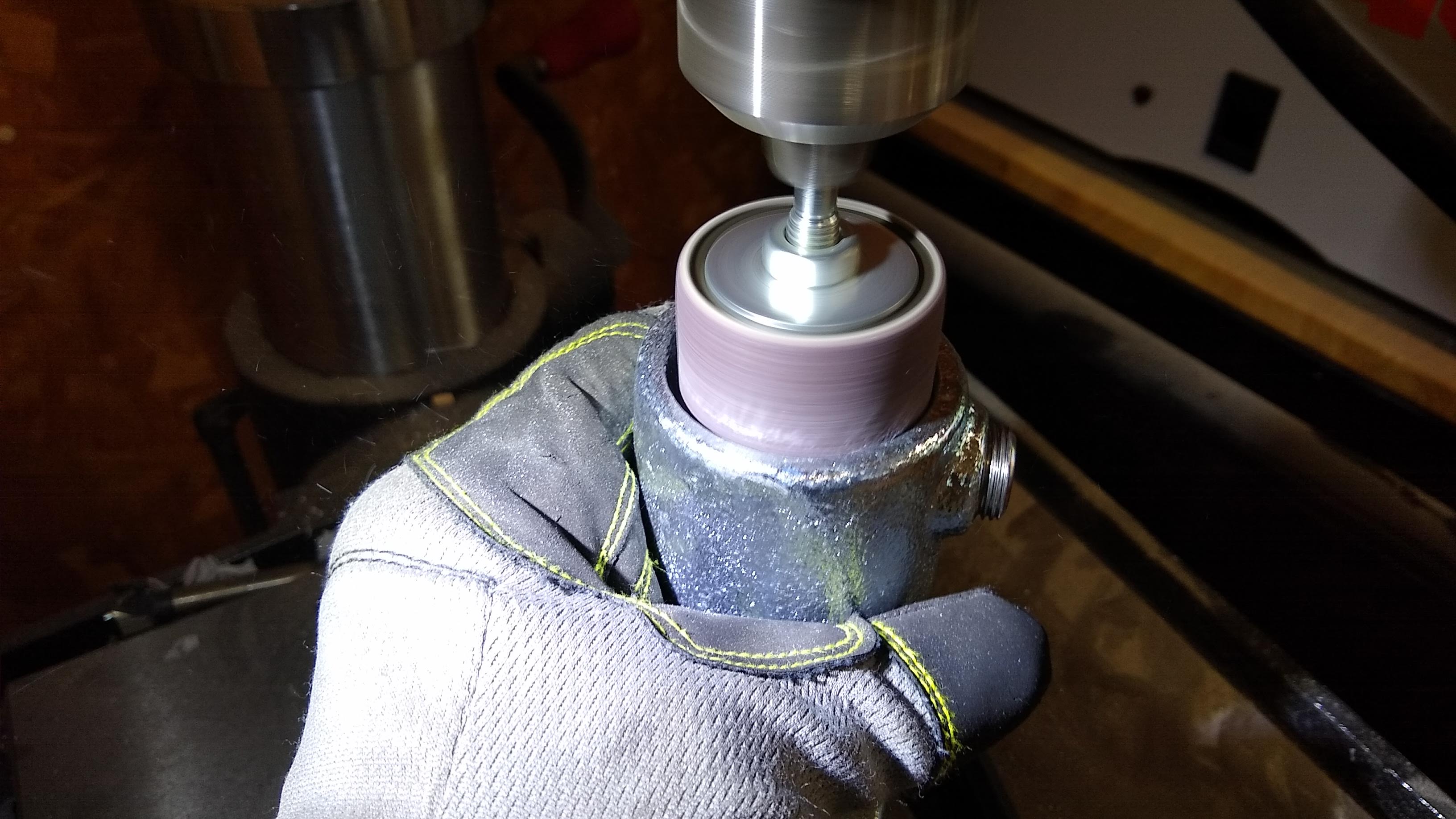
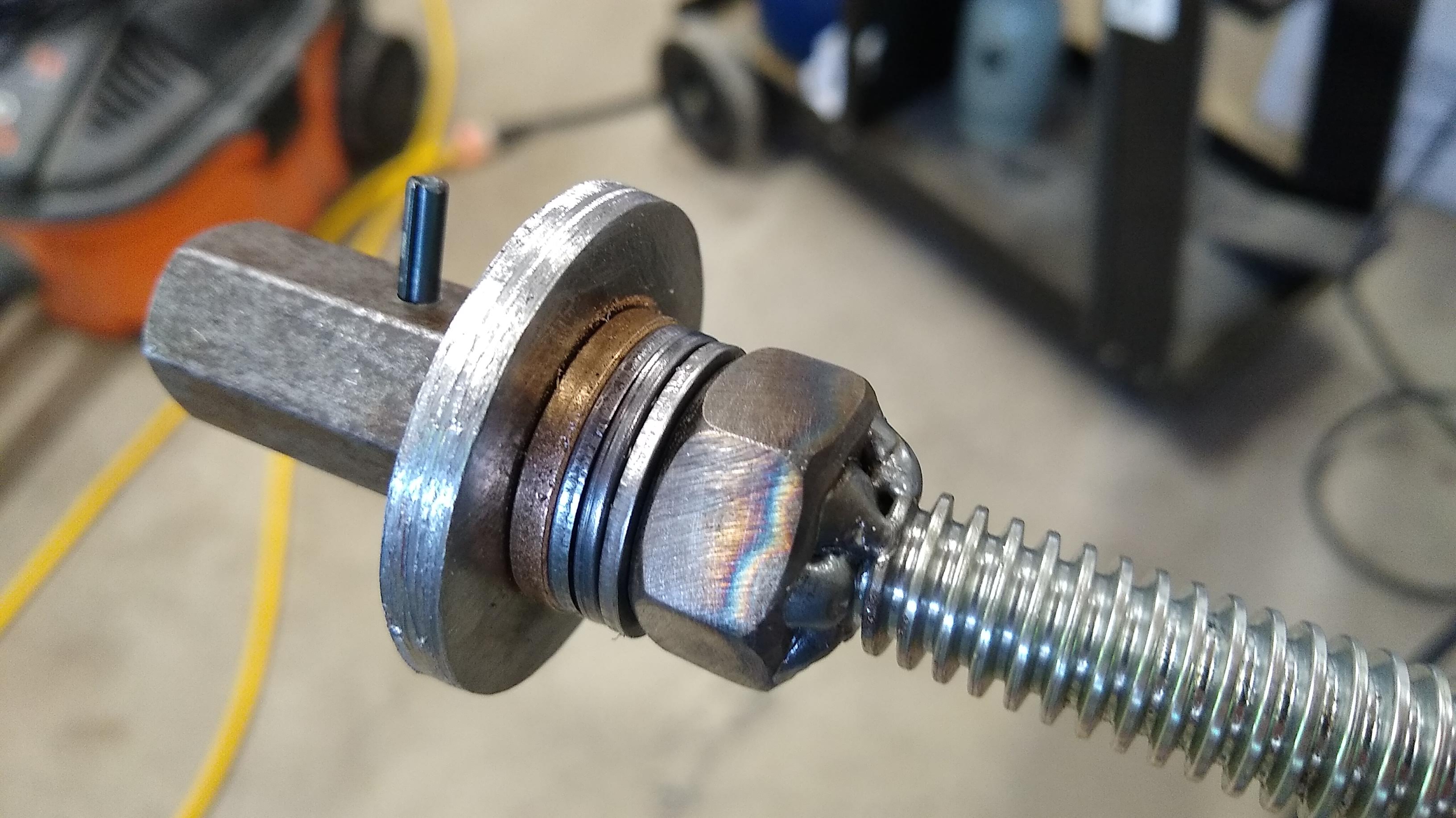
Luckily, 1-1/4″ diameter EMT nests nicely inside the 1-1/2″ stuff, making it easy to make telescoping assemblies; I took advantage of this fact to make the telescoping support arms for the array. Of all the aspects of this build, I’m particularly proud of the panel jack. I did some real mechanical engineering to decide on materials — Euler’s column formula to figure out how much load the screw would take before buckling, and torque equations to figure out if the jack would be able to lift the panel. And it works — I just put a 7/8″ socket on my cordless drill and run the panel up while standing on the ground, safe and sound.
Wiring Things Up
With the mechanical parts of the build largely addressed, it was time to move on to the electrical build. Ironically, this part gave me more pause than the mechanical build. I’m not any sort of engineer, but I’m far more comfortable with electrical engineering concepts than I am with mechanical engineering. But still, I was mindful that I’d be dealing with a lot of power, both on the DC side and with the AC, and coupled with visions of lithium battery fires, I was perhaps just a wee bit scared that I’d get something catastrophically wrong.


There was also the need to pick out the right equipment. This would need to be an off-grid system, as opposed to a grid-tie system. Grid-ties can be simpler since they don’t have batteries; when there’s extra power they just ship it off to the grid instead of storing it locally. My off-grid system would need not only batteries but an MPPT controller to manage charging from the PV arrays as well as an inverter to convert DC to AC. I did a lot of research before finally landing on a Growatt 3000-watt 48-volt hybrid inverter/charger — it’s been discontinued but this one is comparable.
The inverter was an easy Amazon purchase. Batteries, however, were another matter. After a lot of hemming and hawing, I ordered some used 48-volt, 3.2-kWh rack-mount LG batteries from Battery Hookup — they were a one-time deal, so don’t bother to look for them. Using guidance from a video by David Poz, I stripped out the proprietary 14S 2P battery management cards and installed a 100A BMS in each.
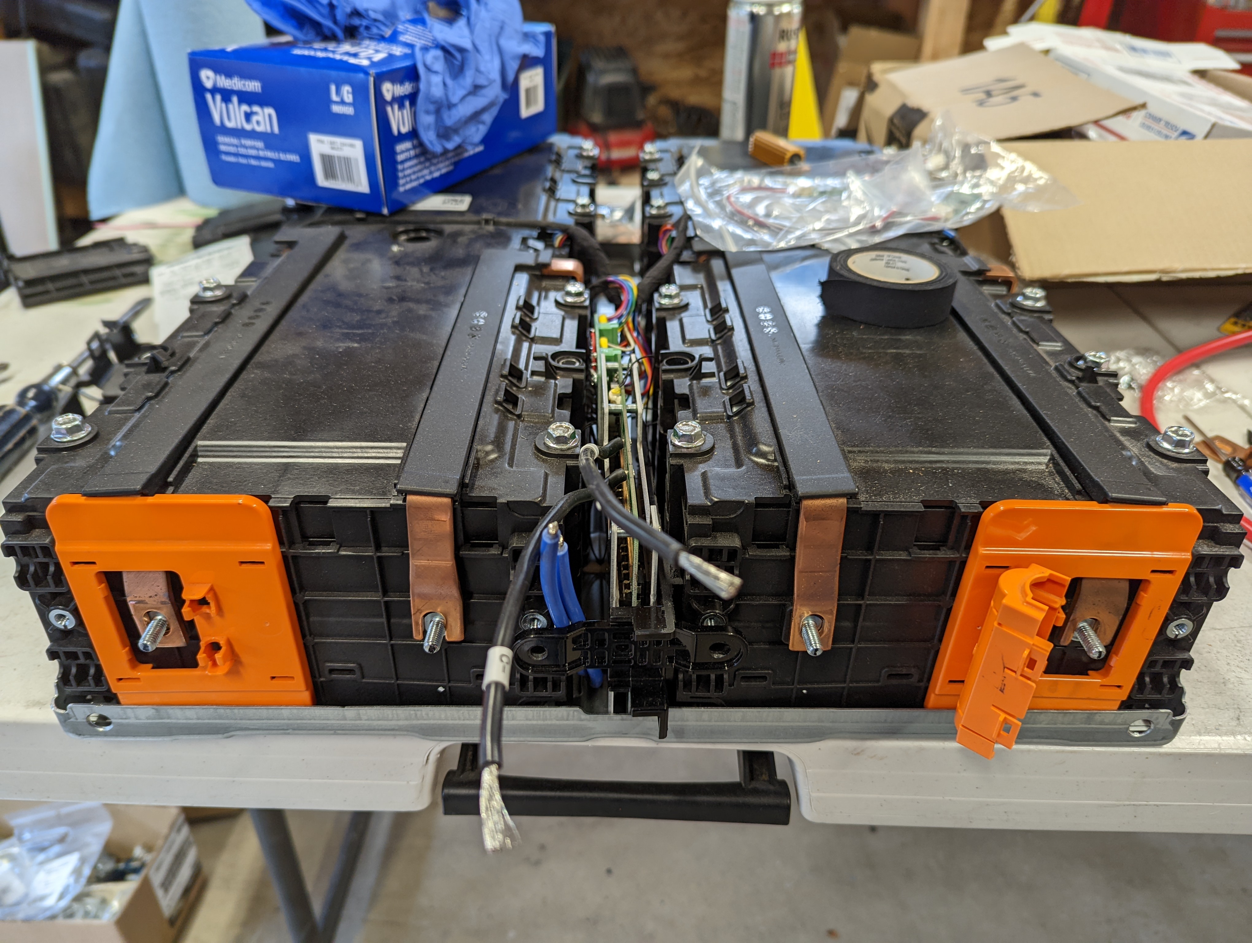
While these batteries work fine for what they are, I have to admit that their homebrew nature gnawed at me. The idea that a simple wiring mistake could result in a fire that would destroy years of hard work was hard to handle. Coupled with the fact that my testing revealed that they only had about a quarter of their original capacity left, I decided that it was time for “big boy” batteries.
There are a ton of rack-mount, 48-volt lithium batteries out there, some of better quality than others. I watched a lot of teardowns by Will Prowse before settling on a pair of Ruixu 100-Ah server-rack batteries. Along with their knock-down bracket racks, bus bar kits, distribution cables, and most importantly, a UL1973 listing, they make a nice addition to my system. Although I will admit that since it was -13°F (-25°C) at the time of writing this, I wish the self-heating option had been available when I bought them.
Fit and Finish – Almost
When I build something or tackle any project, I try my hardest to work up to the professional standards of the job as best I understand them. While I didn’t have much to go on for the mechanical end of this build, and it remains to be seen if the panels will stay on the trailer when it’s being towed at highway speeds, I’ve got a little more experience with electrical wiring. So I tried to make all the wiring as tidy and professional as possible. On the DC side, I invested in a dedicated crimp tool for MC4 connectors, the industry standard for PV applications. I used the appropriate gauge wire for stringing together the arrays, a fused and surge-protected PV combiner box to make connections between the top and side arrays, and proper weatherproof penetrations to get the PV wires inside the trailer. I was extremely cautious with battery wiring, too, using oversized welding cable and a ratcheting crimper to attach properly sized copper lugs, and made sure to use the correct DC circuit breakers to protect the batteries.
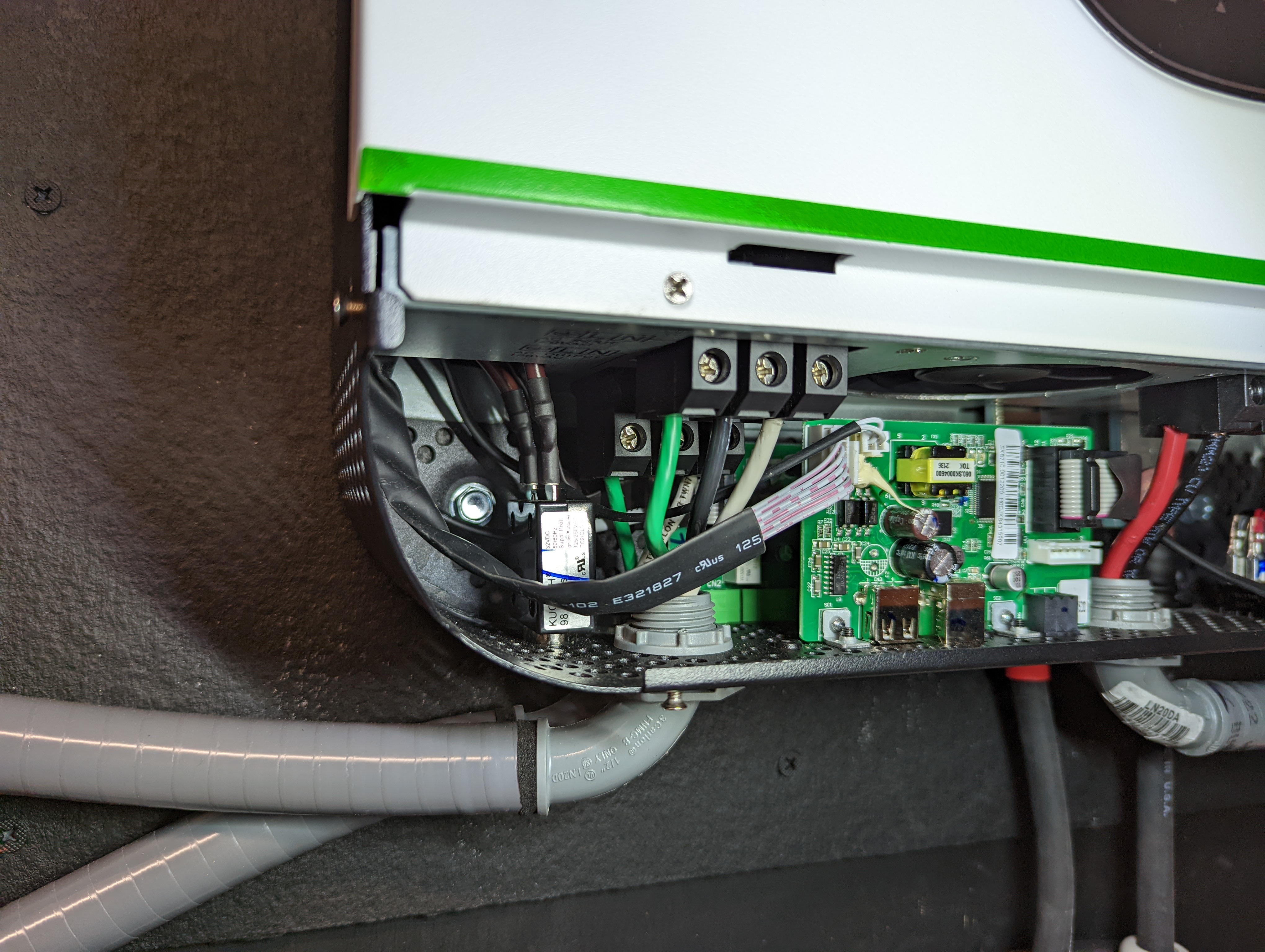
On the AC side, inverter inputs and outputs use industry-standard enclosures and fixtures, and everything is protected by circuit breakers and GFCIs. I am not a licensed electrician, so I can’t vouch for anything I did as being “up to code.” I did try to work to a good level of craftsmanship, though; after all, I don’t want to kill myself or anyone else thanks to a careless mistake. One area I know I have more work to do is grounding. The PV arrays are all bonded together, and everything is tied to the trailer chassis right now. But I need to add a ground connection for off-grid use. Right now, the trailer is grounded through the shore-power connection, but if I were use this away from my house, the ground would be floating, and that’s not good. Also, the Growatt inverter internally connects neutral to ground, which isn’t good since the National Electric Code requires that neutral and ground only be bonded at the service entry point. I need to add a relay that will break the connection between ground and neutral inside the inverter while the trailer is connected to shore power; I have the materials to do it, but the project has been on my to-do list for far too long.
Also on my list are niceties such as a dedicated power drive for the panel jack so the PVs can be retracted automatically in high winds, an automatic start signal to turn on a generator for true off-grid use, and built-in heaters for the batteries. I’m also planning on adding a 12-volt house battery system, because 12-volt power is just so handy to have around.
I haven’t bothered to tote up the costs on this project yet, as doing so would probably spoil some of the fun for me. I think I can safely say that it came in way under the $18,000 I would have spent to get electrical service dropped, so I consider myself ahead of the game. I did invest a tremendous amount of time in this build; on and off over the last three years, I’d estimate I’ve got a couple of hundred hours into it. But it was a real skill-builder for me, and for that reason alone I’m glad I tackled it. That I ended up with the ability to generate and store power is just icing on the cake.


Looks sorta like what the Everlanders did:
https://www.youtube.com/watch?v=lcck1ejlXt8
Wrt “National Electric Code requires that neutral and ground only be bonded at the service entry point. I need to add a relay that will break the connection…”
I think this might be relevant only for Split-Phase systems, which your trailer is not (growatt states it is single-phase). If you study https://en.wikipedia.org/wiki/Split-phase_electric_power#North_America I think you’ll find that this part of the NEC is there to ensure that currents can’t flow across opposite phases in a split phase system, bypassing the neutral (and thus any circuit breakers or GFI). If you’ve got a single phase system, as long as your GFCI’s arent being bypassed by the ground tie, it should be fine to tie neutral to ground at the inverter. I’m just an electrical engineer, not an electrician though. :)
Wrt ground tie, you just want to drive a big long stale in the ground and provide a means of securely coupling your mobile trailer to that extremely immobile stake. Since it’s also protective, tying the trailer frame and any loose bits of metal in the build to ground as well is all to the good. Having a separate ground (aka large piece of metal) at the “house” is also useful if there’s any distance between the trailer and the house (like if you want to move the trailer a ways away to clear tree cover).
I’m not sure about your 12v DC dreams, though. 12V is too low voltage for efficient distribution—every 12V install that I’ve seen (including in RVs and such) ends up with huge gauge wires and hefty copper bus bars. Especially in this age of USB-C, I think you’re better off running at least 24V (one quarter the copper required!) and then putting a cheap USB-C buck converter at every outlet — they are like a buck or so each on Ali, and they can give you the exact low voltage you want at each drop. I’d be tempted to use 48V for the DC run, but 24V seems to be the sweet spot for conversion to the 20V USB-C output voltage.
High current 24V-to-12V buck converters are also cheap if you want to put in a chunky cigarette lighter adapter and run a fridge off it or whatever. Ew.
“it should be fine to tie neutral to ground at the inverter.”
No – definitely don’t do that. I have the same Growatt inverter. When there is no grid input, there will be ~60Vac on the neutral terminal. If an inverter is going to be used in a purely mobile application, it would actually be safer to leave neutral unbonded/floating, otherwise it may inadvertently energize the metal case of all connected 3-prong devices. If the OP is connecting the inverter AC charger/pass-thru input to the grid, it can also pass-through the existing N-Gnd bond at the service entrance, and/or there are dry contacts provided for controlling an external bonding relay.
I somehow missed that this was a grid-tie inverter, I was thinking this was a standalone system. Ignore what I said — the two other commenters (one above, one below) have much more specific and accurate info.
As the commenter above says, definitely don’t tie neutral to ground if you don’t have a 100% certain way to ensure your “ground” is actually at zero potential relative to what you’re standing on.
Nice build …. but if you’re surrounded by tall trees, would it not have been better to put the panels at the top of the trees? I deliberately planted a load of trees here on my island in a circle to eventually put a platform on top, or 3/4 up at least. Sadly, 1/2 of them got ash die back so the had to be in-planted with oaks.
Suppose so, but I originally built it for other locations with better solar aspect, not at my house. It’s just here now because I’m still working on it — no project is ever finished, right? — and I might as well take advantage. Honestly, it’s more useful right now as a way to store electricity either from the grid or from a generator — charge it up by plugging it in for a couple of hours and it gives me a couple of days worth of juice, depending on the load. That it can recharge from the meager amount of sun I get is just a bonus while its parked here.
The Austin, TX electric company had a solar trailer. We used for a few ham radio field days, and it worked very well.
https://austinenergy.wordpress.com/2010/08/19/let-our-solar-trailer-power-your-event/
(After years of service, it had an accident, and is no more)
That is impressive stuff and this paper is great !
Thanks !
Looks great. Hope you have good theft protection on that trailer. Mobile has its negatives. A small company I know designed and built a mobile chem lab for doing field work. One night, someone broke into their fenced area and hauled it off. They hadn’t even gotten pictures or added it to their insurance, yet.
It’s surprisingly difficult to properly lock a trailer, I’ve found. I use a hitch lock plus a wheel lock when stationary. When mobile, there are a lot of places which are /designed/ to come apart under stress. At minimum a ball lock and a locking hitch pin are required, but a dedicated thief can unbolt the hitch ball itself as well. A single-piece forged hitch ball helps cover that link in the chain — and even so I’m not going to promise that any of those links are 100% proof against a good sledgehammer blow.
Perhaps for the author’s installation it helps that system is actually in continuous use — hopefully it would raise alarm if the power went out unexpectedly.
I’m a little lax in that department, admittedly. Pretty safe neighborhood, but that’s sure to change someday and it’s no excuse for complacency. The trailer is in a tight spot that would make it hard to tow away, but there’s nothing keeping a thief from just opening the door and taking what they want. And the stuff in there is expensive, so it might be time to get some locks on there.
Nice project. Whether saving money or not, the immense satisfaction of building something like this, is pretty amazing.
You cant finish a build without a raspberry pi :) How about, a Raspberry pi based monitoring & logging. I have used openenergymeter, and its neat piece of software. And, with HomeAssistant, you can log all the data as well.
I know, right? I’ve currently got a Growatt dongle on the inverter, it connects to WiFi and sends data off to their cloud, which I hate. I’d love to sniff out those packets and see what the conversation is, maybe find a way to bypass the cloud aspect. There’s also RS-485 and CANbus connections that are just ripe for exploring. Should be possible to throw an ESP-32 on the CANbus and integrate the inverter directly to Home Assistant using ESPHome rather than rely on downloading my own data from someone else’s computer.
Yeah, right — in my copious free time…
I have been working on a very similar looking Growatt inverter (SPF5000TL HVM-P, to be precise, from around 2019) for a friend who does not have the dongle, and digging into the modbus docs for it, so I can make an ESPHome-based monitor.
This appears to be the correct modbus documentation for my inverters: https://watts247.com/manuals/gw/GrowattModBusProtocol.pdf
There is a newer set of documentation, but it is incompatible with the older documentation, so make sure you are using the right docs.
I do also have another friend with the same inverters, as well as the dongle. The ShineWifi-F dongle that we are using makes use of a USB-A connector, but uses the D+ and D- conductors for RS232 instead! I made an RS232 snoop device based on an ESP32 and SP3232 dual channel transceiver, that I wrote up here: https://infosec.exchange/deck/@RoganDawes/111595769934719217
I just needed to cut a USB extension cable in half and put Dupont connectors on the wire ends to hook it up to my snoop device. You do need to pass Vcc through to the dongle, so a male-male jumper wire comes in handy.
Building an ESPHome firmware with Wireguard configured to connect back to my own router allowed me to capture the logs of the dongle to inverter (and vice versa) traffic. I was even able to push a new firmware over Wireguard with bidirectional logging enabled on just one UART, which made it possible to determine which side was generating which traffic.
Let me know if you want more details…
That’s fantastic info, exactly what I need to jumpstart this project! Thanks!
Of course, karma hit hard and the whole trailer died sometime yesterday. For some reason the inverter refused to charge the batteries, so they got below the cutoff voltage and the whole thing powered down. Unfortunately, you have to boot the inverter from the batteries, which means I need to drag out my charger and give them a little top-off before I can get things going again. And no — I didn’t get a peep out of the Shine app. No warnings at all, only discovered it this morning when the app reported the inverter was offline.
Not sure what’s going on, other than the universe is punishing me for writing this up. Probably something else too, just haven’t had time to figure it out yet.
https://docs.openenergymonitor.org/applications/solar-pv.html
“Also, the Growatt inverter internally connects neutral to ground, which isn’t good since the National Electric Code requires that neutral and ground only be bonded at the service entry point.”
Are you sure neutral and ground as being bonded internally? Not to sound accusatory – I’m genuinely curious if Growatt revised the design/behavior/firmware, or perhaps you are seeing mode-dependent behavior, as I did. I have been running a pair of SPF 3000TL LVM-48P for 3 years now, and went down a whole rabbit hole of floating neutral, ground bonding, the dry-contacts for external bonding relay, and the US NEC.
When I setting up a single SPF 3000TL LVM in various modes, the only time neutral was being bonded to ground (measured at the AC output terminals) was when the Growatt was in bypass (or maybe it’s called “line”) mode, when grid input is passed to AC out. Specifically, the neutral out and neutral in terminals are connected in bypass mode, but isolated (output N left floating) during inverter mode. In other words, in bypass/line mode, it will appear to have a N-Gnd bond, but is from the NEC-required bond at the service panel being passed through. The ground in and out terminals are always bonded. Hopefully that helps save you some time/effort.
No offense taken — I’m actually not sure of anything regarding the ground/neutral situation. I did a bunch of research early on and managed to lose my notes, but as I recall I found a site that physically examined each Growatt inverter and showed a picture of the bonding strap between neutral and ground. I’m not even close to 100% sure on that, so don’t quote me. But I do recall seeing a schematic in the same document for a relay to break the bonding if the inverter is grid-tied. The relay was supposed to be controlled by one of the inverter’s programmable dry-contact outputs IIRC.
I’m sure I have seen a modbus holding register that controls this relay, but the document that I linked above doesn’t seem to show it, or else I am glancing over it. To say, yes, I think you are right.
My Tesla charges fine in low temperature. Teslas have battery heaters. Lots of them are driven in Scandinavia. I don’t know what your source of news is, but it seems to be reinforcing your pre-existing beliefs.
A battery heater for the OPs set up (you know, like Teslas have) wouldn’t be a bad idea, though. The author mentions this, in fact.
You may have seen https://www.npr.org/2024/01/16/1224913698/teslas-chicago-charging-extreme-cold
That’s a pretty terribly written article; the second half of the article pretty much admits that the first half is sensationalist. The only cited source is a single supercharger station in Chicago which got backed up.
The vast majority of EVs are charged at home or at work, not at superchargers.
For the sake of everyone else:
Only fast charging / DC charging needs equipment. Normal charging just needs a suitable outlet and a long enough cable. Slow charging can be done from any normal outlet, and even at the end of a 100ft 120v extension cord, if that’s how far you park from the nearest source of power. Many people who own or rent a home may already have a suitable outlet that they plug their electric clothes dryer into, though, and it doesn’t take any special EV-specific electrical work to wire up a higher-rated outlet like the kind you use for electric ovens or for travel trailers at RV parks. I don’t generally bake a cake or do my laundry while I’m asleep, so I see no reason an EV couldn’t run off of the same circuit at night.
Damn, you were really waiting for an opportunity to lash out at EVs, weren’t you?
PV = photovoltaic. EV = electric vehicle. This article isn’t even about electric vehicles, whine somewhere else
A very sour whine, at that… flavored with ergot of disinformation….
A very sour whine, flavored with a soupćon of disinformation
Cool build! I have been working on a box truck RV conversion and been putting all the solar panels on top with drawer sliders to increase surface area. I really like the idea of having some hanging down off the side of the truck and then pivot them upwards to create sun shades. Might have to explore that.
https://circuit-break.macrofab.com/t/box-truk-solar-panel-project/51
Sounds like a cool idea to power a food truck! I was really surprised how versatile the conduit and unistrut method of construction is — so many fittings and accessories available to build just about anything without having to custom machine fittings. Not sure I’d want to use them for a project I’d want to be more presentable, but then again, cheap and fast has a beauty of its own.
I will probably have to borrow your idea for the sides of the truck. I want to make sun shades but make them panels. The way you put together the sliding conduit looks robust enough to handle some good side winds (I plan to take it to the beach a lot).
I wonder if those bifacial modules I saw would be good for that? Pick up a bit of light bouncing off the concrete around the truck, if it’s concrete and not asphalt.
Yeah those are cool, Renogy has some panels I am looking at that are bifacial.
That’s one place I wish I did more rigorous engineering. I have no idea how stiff EMT actually is, and whether it’ll stand up to loads from wind or from traveling down the road. I suspect EMT is actually pretty soft, since it’s made to be bent. In compression, like the telescoping supports, my seats-of-the-pants bet is it’s plenty strong. But that’s just a guess.
I suppose what I’m trying to say is to be careful if you’re going to use this construction method around anyone who might be inclined to sue you if something goes wrong. And don’t underestimate either the weight of PV panels — mine are about 41 pounds (20 kg) each — or their sail area under a wind load. Part of the reason I intend to motorize the jack is to automatically stow the upper array if winds get too high, because I feel like a wind coming from the north (assuming the trailer is set to a southern exposure) could flip the trailer. Again, that’s seat-of-the-pants stuff, but the possibility scares me enough to think about ways to prevent it.
Doesn’t scare me enough to properly do the math, mind you…
Exactly, my panels weigh 63lbs, I did some rough math to make sure they wouldn’t rip my roof off and I way overbuilt the rack I currently have.
Looking at this I wonder if a strengthened caravan awning would be an idea if you can mount the panels close enough together?
RV awning controllers already have a concept of retracting when it gets windy, I think they do this with an accelerometer to tell if the vehicle (or possibly a sensor mounted on the awning arm?) is being knocked around by the wind. That might save you some engineering.
For grounds for military generators we just hammered in a ground rod and in a pinch you could also lay one in a trench. As long as all your gear or your home is tied to a single point you are good to go. As far as the neutral bond, if you hook your trailer to a buildings service panel you have the ground neutral tie inside the buildings panel. You should use something like a jumper cable to clamp your trailer ground to the building ground preferrably at the ground rod or the ground bus in the service panel.
The purpose of the single ground concept is that different ground can be at different potentials and could cause currents to flow in the ground conductors that could potentially be really large and flow inside the building. One way around that is to tie all outdoor ground points to each other with underground cable. This creates a ground grid which is effectively a single ground point. Large facilities are grounded this way.