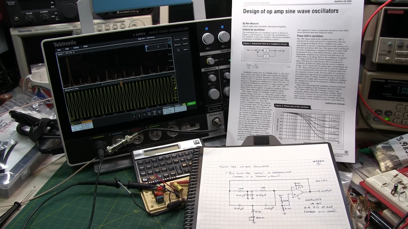
If there’s one thing that amateur radio operators are passionate about, it’s the search for the perfect sine wave. Oscillators without any harmonics are an important part of spectrum hygiene, and while building a perfect oscillator with no distortion is a practical impossibility, this twin-tee audio frequency oscillator gets pretty close.
As [Alan Wolke (W2AEW)] explains, a twin-tee oscillator is quite simple in concept, and pretty simple to build too. It uses a twin-tee filter, which is just a low-pass RC filter in parallel with a high-pass RC filter. No inductors are required, which helps with low-frequency designs like this, which would call for bulky coils. His component value selections form an impressively sharp 1.6-kHz notch filter about 40 dB deep. He then plugs the notch filter into the feedback loop of an MCP6002 op-amp, which creates a high-impedance path at anything other than the notch filter frequency. The resulting sine wave is a thing of beauty, showing very little distortion on an FFT plot. Even on the total harmonic distortion meter, the oscillator performs, with a THD of only 0.125%.
This video is part of [Alan]’s “Circuit Fun” series, which we’ve really been enjoying. The way he breaks complex topics into simple steps that are easy to understand and then strings them all together has been quite valuable. We’ve covered tons of his stuff, everything from the basics of diodes to time-domain reflectometry.


HP-15C calculator on the bench there for the win!!
I agree! My 15 and 16 is still sitting here in my office…
Thanks for the lesson too.
Yeah, won me with the HP calculator. RPN.
Nice for experimental or educational purposes, but unsuitable for production. Without automatic gain control, component drift over time and temperature risk either rising distortion levels or failure to oscillate.
Trying to explain the oscillator in terms of a notch is just wrong. Looking at voltage, the twin-T behaves as a notch when it drives a high impedance load. In the oscillator, the twin-T is feeding a virtual ground at the “-” input of the opamp; what’s important is the phase of the current to that input.
Also known as the original product that launched Hewlett-Packard: the HP100 audio oscillator. Their first customer: Walt Disney, used to help engineer the first stereophonic cinema sound track (“Fantasia”). Also known for its use of an incandescent lamp as part of the gain control that gave it such low distortion output over a wide range of frequencies.
H-P’s first commercial product–sold to Disney–was the HP 200B, based on the HP 200A, the proof-of-concept prototype…
…and the HP 200 design was based on the Wien-bridge oscillator topology, and most definitely not that of the Twin-T.
What is that flat white display that the app note is rendered on? It looks very light weight and portable.
It’s called a dead tree format display, they used to be very popular. You don’t see them very often these days as the refresh rate is terrible.
They used to be very Poplar. :)
This circuit simply amazed me. I never would have thought such a good oscillator could be made with only R and C.
What is the practical frequency range of such a design?
Hm with -45dB notch dip THD should (theoretically) be 0.00316% but 2 potential problems might be of limiting factor: OPamp is not capable of that low of distortion itself (in the datasheet manufacturer is not really bragging with low THD performance soo….), or as i saw in the video, there is still some clipping occurring during adjustment process, which is making this oscillator as complex as Wien oscillator (which is similar in nature just uses 1 order lower H/L pass filter combined into rejection notch filter.