The radio frequency world is full of mysteries, some of which seem to take a lifetime to master. And even then, it seems like there’s always something more to learn, and some new subtlety that can turn a good design on paper into a nightmare of unwanted interference and unexpected consequences in the real world.
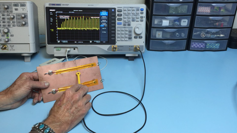
As [Ken Wyatt] aptly demonstrates in the video below, where you put gaps in return paths on a PCB is one way to really screw things up. His demo system is simple: a pair of insulated wires running from the center pins on BNC jacks and running along the surface of a piece of copper-clad board to simulate a PCB trace. The end of each wire is connected to the board’s ground plane through a 50 ohm resistor, with one wire running over a narrow slot cut into the board. A harmonics-rich signal is fed into each trace while an H-field EMC probe connected to a spectrum analyzer is run along the length of the trace.
With the trace running over the solid ground plane, the harmonics are plentiful, as expected, but they fall off very quickly away from the trace. But over on the trace with the gapped return trace it’s a far different story. The harmonics are still there, but they’re about 5 dBmV higher in the vicinity of the gap. [Ken] also uses the probe to show just how far from the signal trace the return path extends to get around the gap. And even worse, the gap makes it so that harmonics are detectable on the unpowered trace. He also uses a current probe to show how common-mode current will radiate from a long conductor attached to the backplane, and that it’s about 20 dB higher with the gapped trace.
Hats off to [Ken] for this simple explanation and vivid reminder to watch return paths on clock traces and other high-frequency signals. Need an EMC probe to check your work? A bit of rigid coax and an SDR are all you need.


When your plane is grounded one should mind the gap, not to fall into unwanted interference.
One of the things I learned when I’d just started doing pcb layout full-time is provide an uninterrupted ground plane, or if that’s completely impossible (double layer board) at least provide a current return trace that’s exactly beneath the loud trace from end to end, for anything over a couple khz.
One of my first jobs many years ago was as a tuning diode product engineer, and I once made a trip to a company that built mechanical TV tuners trying to convert them to electronic tuning. I met with these two old RF design engineers who really knew their stuff. Their mechanical tuners were enclosed in thick stamped metal casings, with separate “rooms” for the RF amp, the mixer, and the oscillator. One of the old guys described how they could move RF currents around in the walls of the case to get more or less coupling by punching a small slot in the case here or there. It was an art form.
Ran into this problem with an ethernet port on a PCB I CNCed. GND connection passed Kicad’s DRC, but the return path for the TX+/-, RX+/- signals went all over the board. Wired a GND jumper and the ethernet port started “magically” working.
Yes, you do use 50 ohm resistors to provide proper 50 ohm RF terminations. You often have to pay extra for good non-inductive ones.
And what is the “desired frequency” of an old 10BASE2 Ethernet system? With relatively random data flowing through it, the spectrum would be pretty broadband with lots of harmonics of the bit rate. You need a proper 50 ohm termination at all of those frequencies; signals at frequencies that are not properly terminated will bounce off the coax ends and screw things up.
I guarantee you that those “50 ohm” terminators you used each had a 50 ohm resistor inside to provide the correct impedance over a broad bandwidth. If you measured a high impedance at DC, it makes me wonder if they were built with a series capacitor to block DC. 10BASE2 Ethernet is Manchester-coded so DC paths are irrelevant. I don’t know why they would block DC unless it had something to do with ESD and preventing ground loops, but maybe someone else can comment.
A 50 ohm resistor is a broadband termination. Some have a series capacitor to prevent dissipation from DC voltage.
I’m with Darren. You do use a 50 Ohm resistor for a 50 Ohm termination. But the termination resistor should match the track impedance, and whether the wire construction on that PCB also has a 50 Ohm Impedance is another matter.
Overall I like the video. It shows quite clearly in a practical setup what is often only shown in theory or in a simulation. My biggest gripe is the camera position. During quite a lot of the video the probe position is obscured because his hand is in between the probe and the camera.
His intentions are commendable, but the explanations are unfortunately rather scant. The issue with such incomplete explanations is that it leaves EMC as “black magic” for many. Much more could have been explained here, and for example, equivalent circuit diagrams could have been used. What a pity.
A similar post were made a couple of days after this, and one of the comments, https://hackaday.com/2024/03/18/proper-routing-makes-for-many-happy-return-paths/#comment-6742637 links a video “What Every PCB Designer Should Know – Return Current Path (with Eric Bogatin)” https://www.youtube.com/watch?v=icRzEZF3eZo which goes much more into details with regards to this.