JTAG is a powerful interface for low-level debugging and introspection of all kinds of devices — CPUs, FPGAs, MCUs and a whole lot of complex purpose-built chips like RF front-ends. JTAG adapters can be quite obscure, or cost a pretty penny, which is why we’re glad to see that [Adam Taylor] from [ADIUVO] made a tutorial on using your Pi Pico board as a JTAG adapter. This relies on a project called XVC-Pico by [Dhiru Kholia], and doesn’t require anything other than a Pi Pico board itself — the XVC-Pico provides both a RP2040 firmware implementing the XVC (Xilinx Virtual Cable) specification and a daemon that connects to the Pico board and interfaces to tools like Vivado.
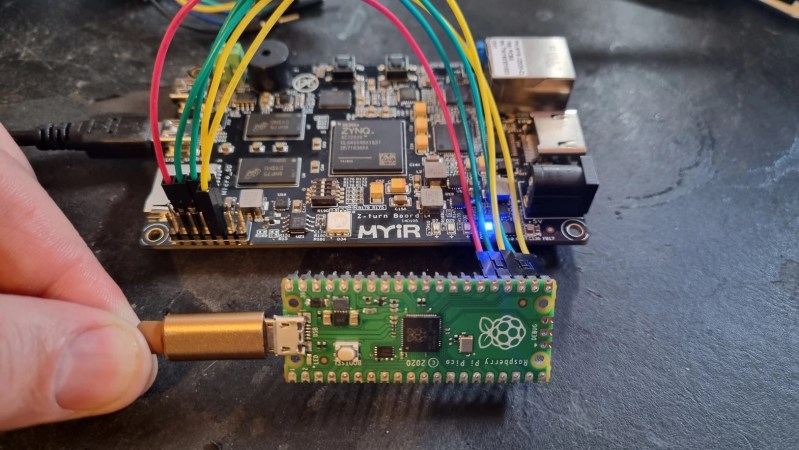
First part of the write-up is dedicated to compiling the Pico firmware using a Linux VM. There’s a pre-built .uf2 binary available in the GitHub repo, however, so you don’t have to do that. Then, he compiles and runs a daemon on the PC where the Pico is connected, connects to that daemon through Vivado, and shows successful single-stepping through code on a MYIR Z-turn board with a Xilinx XC7Z020. It’s worth remembering that, if your FPGA’s (or any other target’s) JTAG logic levels are 1.8V or 2.5V-based, you will need a level shifter between it and the Pi Pico, which is a board firmly in the 3.3V realm.
You just cannot beat the $3 price and the ease of setup. Pi Pico is shaping up to be more and more of a hardware multi-tool. Just a month ago, we covered how the Pico can work as a logic analyzer. A lot of that, we have the PIO peripherals to thank for — an assembly of state machines that even let you “bitbang” high-speed interfaces like DVI. If you’re interested in how PIO functions, there are some good write-ups around here. Lacking a Pi Pico, you can use this board’s bigger sister to interface with JTAG, too.


You ought to add buffers/level shifters also to prevent damage to your 3.3V target when its power supply is turned off before you disconnect the Pico from USB.
Or just 330 ohm resistors, which are easy enough to kludge in – you just need to limit the current through the protection diode. And this implementation of JTAG’s probably slow enough that it won’t matter. You could probably get away with a little lower, but why bother.
Or if you want to be super-lazy you just also sample the JTAG header target voltage and tristate the outputs when it’s gone.
Pico GPIO is 3V3, no level shifters needed. There would be more danger in connecting the pico to a 5V target (less and less common nowadays, thankfully) as the RP2040 pins are not 5V tolerant according to spec (though I bet they’d survive).
“Pico GPIO is 3V3, no level shifters needed.”
It’s to prevent current from flowing from the RP2040 to the VCCIO rail of the target through the protection diode when RP2040’s VCC is 3.3V and the target’s is 0V (off). Protection diode’s recommended max is 10 mA.
If you use a level shifter, the target side’s Vcc will be off, and the level shifter won’t do anything. Obviously you need a level shifter that can tolerate Vcc on one side being 0V while the other is powered.
Is there a project similar to a Bus Pirate based on the Pico yet?
I guess I could have searched that myself. https://git.lain.faith/sys64738/DragonProbe
If you are in need of a quick serial adapter to your devices I can recommend you. I is cheaper to buy a pico then a ftdi
https://gitlab.com/mrnice/pico-pi-serial-bridge
RPi also doesn’t have that nasty history of deliberately bricking customer devices…
I modified the code to use an Adafruit QT-Py RP2040 which is a bit more expensive but a lot smaller. The code is at https://github.com/hamslabs/picoprobe