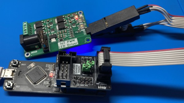
Showing the ESP-Prog-Adapter board plugged into the ESP-Prog adapter, wired to a SOIC clip, that then attaches to a PCB under test

ESP-Prog-Adapter Makes Your ESP32 Tinkering Seamless

Did you ever struggle with an ESP32 board of yours, wishing you had exposed that UART, or seriously lacking the JTAG port access? If so, you should seriously check out [0xjmux]’s ESP-PROG-Adapter project, because [0xjmux] has put a lot of love and care into making your ESP32 hardware interfacing a breeze. This project shows you how to add JTAG and UART headers with extra low board footprint impact, gives you a KiCad library to do so super quickly, and shares a simple and helpful adapter PCB you can directly use with the exceptionally cheap Espressif’s ESP-Prog dongle you should have bought months ago.

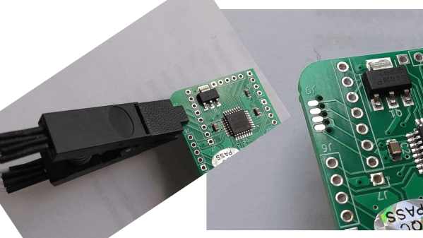
The hardware is perfect for ZIF no-soldering interfacing – first of all, both UART and JTAG can be connected through a SOICBite connection, a solderless connector idea that lets you use SPI flashing clips on specially designed pads at the edge of your board. For the fancy toolkit hackers among us, there’s also a Tag Connect symbol suggested and a connector available, but it carries JTAG that you will already get with the SOICBite, so it’s maybe not worth spending extra money on.

Everything is fully open-source, as one could hope! If you’re doing ESP32 hacking, you simply have to order this board and a SOIC clip to go with it, given just how much trouble [0xjmux]’s board will save you when programming or debugging your ESP32 devices. Now, you don’t strictly need the ESP-Prog dongle – you could remix this into an adapter for the Pi Pico board instead. Oh, and if designing boards with ARM CPUs are your thing, you might benefit from being reminded about the Debug Edge standard!

SOICbite: A Program/Debug Connector For An SOIC Test Clip

The problem is well-known: programming and debug headers consume valuable board space and the connectors cost money. Especially troublesome are the ubiquitous 100-mil pin headers, not because they’re expensive, but because they’re huge, especially along the z-axis. If you’re building miniature devices, these things can take up a ridiculous amount of space. With some clever thinking, [Simon Merrett] has found a way to re-use something many of us already have — an SOIC-8 test clip — to connect to a special footprint on the PCB without requiring another connector. He calls the system SOICbite.

The SOIC clip attaches to a footprint consisting of eight pads, four on each side of the PCB, plus five non-plated-through holes, which serve to anchor the clip in place. The idea of mating a PCB footprint directly with a removable connector isn’t entirely new — Tag Connect has been doing this for a while, but the connectors are expensive and single-sourced. On the other hand, SOIC test clips of varying quality are available from a number of vendors, including dirt-cheap deals on your favorite websites. The one disadvantage we can see is that the SOICbite footprint must be at the edge of the PCB to properly mate with the clip. The savings in space and cost may well make up for this, however.

[Simon] has made his KiCAD footprint available in a GitHub repo, and has offered to host footprints for any other CAD package there as well. So, fire up your preferred tool and draw one up for him to get these things widely adopted, because we think this is a great idea.

For the commercial alternative, check out our coverage of Tag Connect back in 2014.