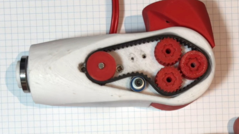
We’re not certain whether [Paul Gould]’s kid’s prosthetic elbow joint is intended for use by a real kid or is part of a robotics project — but it caught our eye for the way it packs the guts of a beefy-looking motorized joint into such a small space.
At its heart is a cycloidal gearbox, in which the three small shafts which drive the center gear are driven by a toothed belt. The motive power comes from a brushless motor, which is what gives the build that impressive small size. He’s posted a YouTube short showing its internals and it doing a small amount of weight lifting, so it evidently has some pulling power.
If you’re interested in working with this design, it can be downloaded for 3D printing from Thingiverse. We think it could find an application in plenty of other projects, and we’d be interested to see what people do with it. There’s certainly a comparison to be maid over robotic joints which use wires for actuation.


“There’s certainly a comparison to be maid over robotic joints which use wires for actuation.”
The comparison that is made depends upon the task performed by the maid!
Homophones can be fun!
Neat. compact design. Took a moment to figure it out.
I wonder what happens if one of the driven sprockets skips a tooth, or the belt spacing isn’t quite right.
Please give the following figures:
1. what were those weights, and what distance from the pivot were they at, so we can calculate the kg*cm torque
2. what is the reduction ratio in the cycloidal part of the system? And are there reductions anywhere else, I’m thinking NOT as the pulley driving the belt looks the same radius as the three cam-back pulleys?
Neither the YT vid nor the thingiverse page seems to quote them.
P.S. to my understanding that cycloid is one where the cycloid disc is vibrated by 3 eccentric cams but does not itself rotate, then the outer casing rotates alone, different to the usual situation where the cycloid is wobbled by one cam and rotates itself against a fixed outer casing as it wobbles, with the torque then being output via pins which tke the rotay motion rom the disc without the wobbling.
Thanks
No.
You’re welcome.
Sorry, I don’t get the use of the 3 shafts. To me it could have been just 1 shaft instead of the 3.
1. The 3 have to be timed properly so that they are all shifting the eccentric in the proper direction and time.
2. The white part has 3 holes for the shafts whose ends run in the white plastic – there are no bearings for the shafts in the white plastic.
3. The silver metal large ID bearings on the white plastic are for the red pivoting arm and don’t know why there looks to be 2 of them.
If you use only one eccentric shaft in the center, (as most hobby cycloidal gears do) then you also need extra pins to prevent the cycloidal disk from rotating, and the disc has to make it cycloidal movement around these pins, which is a bit of a sloppy process. This is prevented by using three eccentric cams. Nabtesco is a big brand in gearboxes for robotics, and they have been using this arrangement extensively. They patented it somewhere in the ’80-ies
thanks
If this is an elbow joint, then on which side is the wrist, and on which side the shoulder?
The tapered section on the end of the white plastic seems to indicate that it goes to the wrist. If so, then the motor is not placed in the optimal position. You want to keep all weight as close to the “base” (in this case the shoulder) as feasible, and that means (If my interpretation is correct) to put the motor in the red side.
Apart from that detail, this section looks quite well made. I’m curios what the whole thing would look like.
If this is for actual prosthetic use, the weight should be similar to a biological arm. And the length of red part is what it is.
Depending on how much of the arm is missing, this might be the only place to place the motor.