The solderless breadboard is perhaps the electronic hobbyist’s most commonly used tool, but let’s be honest, it isn’t exactly anyone’s favorite piece of gear. Even if you’ve got an infinite supply of jumpers in just the right size, any mildly complex circuit quickly becomes a nightmare to plan out and assemble. To say nothing of the annoyance of trying to track down an intermittent glitch, only to find you’ve got a loose wire someplace…
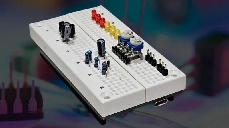
The Sandwizz Breadboard hopes to address those problems, and more, by turning the classic breadboard into a high-tech electronics prototyping platform. The Sandwizz not only includes an integrated power supply capable of providing between 1.8 and 5 volts DC, but also features an array of integrated digital and analog components. What’s more, the programmable connection system lets you virtually “wire” the internal and external components instead of wresting with jumper wires.
To configure the Sandwizz, you just need to connect to the device’s serial interface with your favorite terminal emulator and work your way through its text-based menus. You can also export a netlist file from your KiCad schematic and upload it into the board to make all the necessary connections automatically. This lets you make the leap from concept to physical prototype in literally seconds.
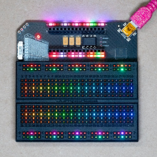
If all this sounds a bit familiar, it’s probably because the Sandwizz clearly has a lot in common with the Jumperless. Created by [Kevin Santo Cappuccio], Jumperless uses an array of analog crosspoint switches to connect devices on the breadboard without the need for any jumpers (hence the name), and also uses a serial interface to configure the netlist. Jumperless uses RGB LEDs to indicate connections directly on the breadboard, and features some integrated analog and digital diagnostic tools, as well as the ability to take voltage and current measurements.
On paper it does sound like the Sandwizz offers some advantages over the Jumperless. The collection of onboard circuit components sounds very interesting, but the documentation seems pretty vague on what’s included. The expandability that lets you connect multiple Sandwizz boards together to create a larger workspace also looks nice, but depending on how much these things cost, having more than one might be a tall order for the average hobbyist.
But the biggest difference between the two is that the Jumperless is open source hardware and is available for purchase right now, while the Sandwizz is still working its way towards a Kickstarter currently scheduled for early June. The limited documentation and AI-voiced video below the break don’t exactly instill us with confidence, but to be fair, we can’t pass judgement on it until we can see how it works in the real-world. In the meantime, we’re interested to see where this new competition in the world of smart breadboards will take us.
Thanks to [paulvdh] for the tip.


At a first glance, the concept is attractive. However, I think it’s ultimately the wrong direction to go.
The point of breadboards is physicality and understandability. I can see where connections go, I can modify them with my hands, everything is direct and immediate. Yes, configurable connections offer advantages, especially in making circuits less convoluted, but so do larger breadboards that allow you to space out your components more, as well as precisely cut wires in varying lengths that sit flush to the breadboard.
So ultimately, I think these attempts are futile, as they look fancy and seem convenient and high-tech, but they lack the ability to understand how a circuit is wired by just looking at it. They’re also quite expensive (which they need to be due to the sheer amount of hardware required) and pretty small, in contrast to conventional breadboards, which are just very cheap, so it’s completely fine to have, say, 30 of them.
If I was going to drop a bunch of money to solve the breadboard wiring issue, it would be on a desktop auto wire cutter/stripper. As a tool it would see more use than just breadboarding, and keeps the circuit visibility feature of them. Most likely quicker too.
When I originally saw the Jumperless my first thought was “ooh pretty, would be a fun toy for a few minutes”, but like you say, the price isn’t able to be low enough for a toy that lasts less than a day.
So a CNC Wire Wrap Tool.. I’d have LOVED that back in the 80’s when I was doing that..
Cap
They existed.
> they lack the ability to understand how a circuit is wired by just looking at it.
It’s going to sell well to the instructable crowd and to a lot of educators as well. These people want a “recipe” to follow, to make others do the motions according to a list of instructions, because they confuse replication with understanding or learning.
These people are going to take the netlist as given magic and copy/paste it over without even trying to grok what the connections are doing. When they put the components down and do what appears to be magic rituals on the computer, lights start to blink and motors start to turn, and people go “Wow that’s so cool!”, and then they feel like they’ve done something special for the kids.
Yep, my thought as well. If you go through the work to set it up with a computer, you might as well just use a simulation tool.
Which will probably give you better results, as I can’t imagine that analog mixing every signal will do great things to signal integrity. Some circuits really don’t enjoy an extra few ohms here and there.
And now you need to worry about frying or damaging the fancy expensive breadboard. Vs a 2$ breadboard that basically the only to damage is to stick a soldering iron into, or overheat somehow.
Also, this doesn’t *at all* solve the loose connection problem (which by the way the solution is get a new breadboard, or sharpie over the known bad contacts). You still have physical contacts on the board, which can be oversprung or worn out. Fewer of those contacts since no jumpers sure, but still a contact for every pin of every part.
This seems like a solution looking for a problem. Which given its a Kickstarter, kinda makes sense (nothing against trying to make and sell something, I’ve actually got a few projects in the pipeline I night try to sell. But I want them to actually be worthwhile for people to buy, not a toy that just sounds cool)
>damaging the fancy expensive breadboard
Breadboards are consumable items anyhow. They become corroded and wear out from insertion and removal of components. Eventually they all become flaky and you have to buy another one.
Yes, they are consumeable. When they cost a few dollars to very low tens of dollars, that’s a reasonable cost of doing business. When they cost several hundreds of dollars, that becomes much more of a burden.
The more common problem with breadboards is current capacity in the connectors.
Particularly in the super cheap versions, an opamp driver can overheat the connectors.
I designed the breadstick to build on the best parts of breadboards, something that can be understood at a glance.
https://hackaday.io/project/191916-raspberry-breadstick
A neat idea with a (excusable) poor execution. As “f__” says in another comment, you could have a bunch of traditional breadboards for the same price of a small one of these.
Most of my projects involve a microcontroller; therefore, I generally use a software simulator to rough-out a partial I/O subsystem. I “may” use a solderless breadboard to sanity-check the simulation with real components, but then only to the point where I can use my digital oscilloscope to verify the tie-point to the uC … a time where discrete resistors are substituted to potentiometer values were used simulator.
Everyone has a different view regarding prototyping and maybe a big divide exists between trained engineers and hobbiests as degreed individuals often think at a system level and design at a modular level with the idea of (somewhat) seemless intergration to a completed project. My experience assisting self-trained electronic hobbyists is they stay at the project level and then tinker with various aspects of the design until the composite system begins to work acceptably.
At some point, very experienced hobbiests do often “flip” into a systems mindset.
And still to this day, no one has remade the bread board for larger components. Everyone makes them for 0.300 in the center and holes for only 5 wires. You can’t even wire a pi pico without loosing a quarter of the bread board space.
Yep, never understood that. When I got my first Mbed in 2011, I took one of my breadboards from college, cut it down the middle, and essentially made two breadboard halves that could be at whatever spacing I wanted.
That’s why I make my PCBs SIP, so that they can plug into the edge of the board or, with right angle connectors, into the middle and not take up *all the space*.
You can of course buy 2 breadboards and fix them to a base board at the spacing required for your pico or other wide DIP board
I think it’s going to sell very well. This is directly addressing a particular issue with electronics education in general. That is lowering the barrier for raising awareness in people. Making breadboarding simpler and faster through abstraction into software is a great way to inspire people, because it looks like magic – and it works like magic too: all you need to do is copy/paste the project’s wiring code and insert your components the same way, and you can replicate even complicated designs without the tedium.
You can share the design on your online platform of choice and have people without prior training replicate it exactly. This is useful, because it means that educators, even without any expertise in electronics, can begin teaching on the subject – and people without prior experience can follow along just as easily.
Combining software defined breadboarding with maker-style pre-built hardware modules and breakout boards, with shared code that can be copied by anyone and everyone, enables people to achieve impressive results in minutes without years of training in embedded systems design or electronics. You really don’t need to know how a transistor or a resistor works to make things light up or move around – you can skip all that and get ahead much faster, because these basic problems have been solved already for a century now. It’s all about lowering the barrier for entry into electronics – by reducing the amount of stuff you need to learn.
Raising awareness is important, because it teaches people what can be done with readily available products you can buy off the market, and inspires people to follow the examples and replicate the projects for themselves. That is also a positive feedback loop for the designers, because it means there will be more people wanting the tools for the task: it will increase the demand for the breadboards and the hardware modules sold by other makers.
This topic is also one of the underpinnings of the fourth industrial revolution, or Industry 4.0 as they put it.
Instead of being limited to design your factory or your process from the ground up, you can have a platform of pre-made components that can be put together in a software-defined fashion. It’s almost like Software as a Service, but instead it’s Industry as a Service, where you’re free to imagine whatever you want to do and the components to do it are provided off-the-shelf. All this is managed by IoT in the cloud, so you don’t have to bother with managing your IT. You just subscribe to the platform and they do it for you.
In this manner, the less you know the better off you are, because you’re not wasting time doing things you can simply buy or subscribe into. That’s the lesson you learn from the software defined breadboard as well – the more you can virtualize away, the faster you can get things done by skipping the steps where you have to tediously cram it into your head and then manually perform the actions yourself. All you should do is imagine it, because the solutions already exist.
When prototyping on breadboards I often have only a schematic as a basis and decide the layout on the go. Sometimes not even a schematic if the circuit is not too complex.
This tool is useful for circuits you designed on a computer already, but I’d say a lot of breadboard circuits are actually about testing an idea quickly, or just a few components. For that wiring needs to be fast, so a nicer idea would be if you could just virtually “paint” over the holes to program the connections. Maybe while pointing a camera/smartphone on it, to capture the movements of a pen and then create a wire programming out of it.
Regarding the cloud in IoT and using third party services, that’s not a good idea, it makes your system less reliable, and prone to contract changes, software changes, constant costs, hacking etc. It’s more convenient to have a simple local open source software stack on a local server, that is not connected to the Internet.
If you actually need an Internet connection, you could have specific services instead of exposing IoT devices directly, which reduces the attack surface.
You don’t need to “test an idea”, because the solution already exists in a repository in the cloud. You just copy/paste it to your board and lay the components down as prescribed. The idea is to outsource the thinking to other people, or even an AI – you just say what you need and the solutions are provided.
You have excess faith in the quality of engineering in random repos.
Building circuits with predefined modules is well and good, until you use a module that isn’t well thought out. Then ur troubleshooting a circuit you never bothered to understand, perhaps on an edge case. Worse if you don’t have the fundamentals. I’d guess about 10% of artsandcraftsaDay readers are EEs.
Works on opamp circuits, to a degree. But opamps are easy and most opamp modules are old and well understood.
>constant costs
In-house IT is a constant cost. You have to hire people and maintain facilities, servers, software etc. Not binding yourself down with these rigid structures allows you to pick the lowest bidder anywhere in the world. Vertical integration of business is just integrating overhead into your management structure – lean manufacturing is the modern solution.
“The value of adding activities are simply only those things the customer is willing to pay for, everything else is waste, and should be eliminated”. That is to say, your business should be simply about taking money from the customer and using it to buy the things they need from the market, like an industrial service broker. That way the cost of doing business is passed directly to the customer and you’re not bound to a particular platform or service – the customer is. The value of your service is providing access to industrial services, not producing them yourself.
Think about it – if you already have solutions, such as an Arduino sketch and modules on a software defined breadboard that performs the functions your customer desires, then you can pass that on to the customer directly. That saves a lot of engineering and and the customer gets the thing they described quickly and efficiently.
The next step would be for PCB manufacturers to take that software definition and turn in into a physical backboard for your device, so you can go directly from prototype to product in a single step.
LEGO factories.
“LEGO engineer” used to be a mocking term meant for saying you’re not a real engineer because you can’t design and/or build things outside of pre-built parts and construction systems, but nowadays it’s just wasted effort: everything is “LEGO”, so why should you re-invent the wheel? Training yourself to work outside of the system is just a waste of time when you can simply buy into the system. In this manner, everyone can be an engineer – not just those who spent ten years in school.
No, not even close.
Most people can’t define engineer and are innumerate.
Engineering fields do become somewhat cookbook as they age. But even glorified ditch diggers (civils) have to understand how the legos they put together work internally. Even the drainage guys.
with breadboards i feel im always up against the speed constraints of them. originally just the capacitance of the contacts. but now you got the constraints of whatever programmable crossbar switch you are using. and if you go out of spec for that crossbar you are going to fry things. i cant help but think the gadget has a niche that most of us have far surpassed. you can improve breadboards, but i dont think this is the way to do it.
For me people complaining about the capacitances of a solderless breadboard belongs more or less in the same category of people who says 90-degree angles on a PCB is bad. Either they are ignorant or they are doing stuff in the upper-upper echelon of electronics design.
A solderless breadboard has about 4 pf capacitance between two adjacent signal rails according to my own measurements and also a video by eevblog-Dave from many years ago. That is in the ballpark of the capacitance between two pins of a normal DIP IC.
low speeds are fine for blinking leds, but if you need some high speed signaling, you are going to run into problems.
What are you on about?
90 degree bends in traces ARE bad for any signal not basically DC.
It’s 2024, a MHz or 10 is not a high frequency.
Hardly ‘upper upper echelon’.
FYI Intel was stuck with a 25 MHz external clock for the processors back in 486 days for lack of one old ham on staff. To point to the 90 degree bend in the overlong bus of the day. Why the DX2-50 existed at all. They only got 25 MHz with lots and lots of ground plains, other expensive trickery.
Granted, we’re off topic. You aren’t going to run a halfway modern processor bus over any breadboard.
I have some ArduEZ RPi bread boards. They are pretty neat. https://arduez.com/ A full switching matrix always seemed too complicated but Sandwizz seems to have done it. I wonder what they will cost.
I don’t remember what it was called, but as a bobling I had a (second-hand) electronics kit where you made circuits out of a grid of little plastic cubes with the symbols printed on the top (including straight wires / corners / T junctions etc), so that the assembled circuit was also a diagram of itself. I’ve thought before that you could cross-breed this with a breadboard for more serious use.
IMO the biggest drawback of breadboards isn’t the messing around with jumpers; at the design stage, you’ll be doing some version of that anyway, even drawing a schematic in KiCad. The bigger problem is that the breadboard topology is nothing like the real circuit you’re designing, so you have to figure it out all over again when it comes to the “production” version.
I might be interested in a fancy breadboard if it solved that problem, but not if feature creep turned it into a whole new thing I had to think about. For me the value is in removing friction, not adding more.
Yeah, it can be a bit of a hassle constantly switching between schematic, breadboard and your pcb. Your description made me think of this lego like breadboarding system: https://www.5eboard.com/product/advance-board/
i kind of wanted a system where you could route signals with dip switches. and thus get rid of most of the jumpers for power, ground, etc. effectively anywhere where you have busses next to eachother you would have a switch that could connect or disconnect them. more hands on than software controlled crossbar.
I managed to find that old kit online:
https://en.m.wikipedia.org/wiki/Gakken_EX-System
I was delighted to discover it was made by Gakken (the Zeus of model kits), which explains so much. I now realise this is why I’m compelled to buy everything Clockwork Pi makes – I’d already noticed their kits were Gakken-like, but it turns out they were literally riffing on this specific kit, down to the signature knobs on the sides.
I find wire-wrapping more convenient than breadboards. Most chips nowadays come on breakout boards or evaluation boards – you couldn’t plug SMD chips onto breadboard anyway. Then I just hotglue the breakout boards onto a piece of cardboard and use wire wrapping to make pin connections. Wraps are more reliable and more versatile than breadboard jumpers.
The WSU-30 wrapping tool and its cheap clones are quite effective.
I’ve been tracking this since it became available. What this basically solves is not so much the speed or the ease of use – for that it’s just an expensive toy – but the breadboard wires that get loose and the long troubleshooting that goes with that it.
I also don’t see how the breadboard chaining can possibly work well. A bus is used to glue the analog switches together – just 6 pins is not enough to wire a 16 wide bus like Kevin uses. But my main concern is that my applications involve motors, and analog switches simply cannot carry that much current.
Normally I just end up skipping the whole breadboard phase and going straight to a pcb with a whole bunch of solder jumpers. If space is not a concern, that means it also serves as a first version which be quickly tested for EMI/EMC.
I’ve used solder less breadboards extensively in the past.
They offer quick prototyping and allow you to learn to read and write circuit diagrams.
This “solution” seems to take away the learning aspect compared to the visible hands-on approach. And also forces you to use a computer.
One problem with breadboards is imperfect connections. Resistance and capacitance of the contacts and the resistance and inductance of the long wires.
This limits power and frequency of your circuits. This solution doesn’t seem much better. The multiplexers probably distort the signals even more.
Another problem is that you can only use through hole components or you need to solder them onto an adapter board.
This “solution” doesn’t address that.
An integrated power supply is a good idea. But I would prefer one that don’t require a computer and has multiple outputs (including negative ones).
This seems like a “solution” looking for a problem.
Offer me a solderless breadboard where I can just click on/in smd components and I’ll buy it. But I doubt something like that can be made practically and affordably. Maybe people can come up with creative solutions. Such as a solderless adapter board for SMD compontents.
A book on analog and digital circuit design would be a much better investment. Since the miniaturization of components is progressing rapidly, the breadboard will eventually be a thing of the past anyway. Unless you want to buy breakout boards for every component.
this. You can’t really breadboard anything anymore without breakouts for the components.
As such I only use breadboards for quick and dirty hookups. For everything else I go ahead and get a PCB cut. Even if it isn’t perfect on the first cut it has several advantages.
First is getting a first rev of the design completed makes all subsequent work pretty easy; second it’s not that difficult to haywire any mistakes you may have made; third is that I always find things that I want to change along the way so a second cut of the PCB is inevitable anyway; and last stupid mistakes like the wrong footprint, etc. surface immediately.
The downside of course is cost.
i don’t think this solves any problems. the interconnect is a bad idea, because it means you’re designing a circuit with an interconnect in it. when you pull your components out of the breadboard and solder them together, now you’ve got a different circuit that’s never been tested. that’s inevitable a little bit because of capitance and so on, but this is just a ridiculously large effect.
and the power supply…i have what was an expensive breadboard with an integrated power supply. guess what, the power supply is blown and the breadboards are worn out from the era of resistors with thicker leads. the much cheaper breadboards that i have a pile of are far more useful. i never have any trouble connecting my bench supply to a breadboard, and some of my old cellphone chargers have appropriate copper wire soldered onto the end that makes them easy to use with a breadboard.
the thing is, i don’t think this is just a not-useful-to-me prototyping tool, i think it’s actually a representative of a problem facing electronics education in general. my kids have been exposed to a bunch of different kinds of toys that are meant to be educational. they focus on *novelty*. no one wants to make a replica 100-in-1 box with the cardboard substrate and the spring terminals. a lot of products these days means a single component has to have a big plastic box and expensive magnetic contacts or something. or even a microcontroller for each component. so they have to have a low number of components. you can’t really build much.
they also focus on making it so the circuit can’t fail. the LED isn’t a physical component with voltage and current requirements, but rather a logical component, on or off, with a built in power supply that is much more complex than the visible resistor we used to have.
it might be justified if it was more fun, but my kid got bored of these extremely limited kits right away. they replaced the frustration that drove kids away 30+ years ago with a rigid lack of possibilities.
i think i’m whining about the blinkie-fication of electronics. if you aren’t making oscillators and trying to fathom transistors and capacitors and instead limited to won’t-fail circuits that can be driven by an arduino…at the end of the day most people just make blinkies, and have a hard time fathoming anything else. just a huge gulf of potential between the blinkie and the PC.
A ZIF breadboard (zero insertion force) would seem more useful to me