[Stephen McNamera] found a schematic for a grid leak radio online and decided to throw together a few tubes on a piece of wood and see how it worked. As you can see in the video below, it works well. The video is a bit light on details, but the web page he found the plans on also has quite a bit of explanation.
The name “grid leak detector” is due to the grid leak resistor between the grid and ground, in this case, a 2.7 megaohm resistor. The first tube does everything, including AM detection. The second tube is just an audio amplifier that drives the speaker. This demodulation method relies on the cathode to control grid conduction characteristics and was found in radios up to about the 1930s. The control grid performs the usual function but also acts as a diode with the cathode, providing demodulation. In a way, this is similar to a crystal radio but with an amplified tube diode instead of a crystal.
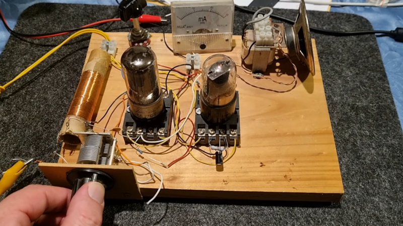
It looks like [Stephen] wound his own coil, and the variable capacitor looks suspiciously like it may have come from an old AM radio. The of the old screw terminal tube sockets on the wood board looks great. Breadboard indeed! What we didn’t see is where the 150 V plate voltage comes from. You hope there is a transformer somewhere and some filter capacitors. Or, perhaps he has a high-voltage supply on the bench.
While tubes are technologically passe, we still like them. Especially in old radios. Just take care around the high voltages, please.


What are those nice tube sockets ?
Those look like relay sockets to me. They’ll fit octal tubes and I’ve used them as tube sockets in the past.
Yep, thankfully they’re still very common and available brand new, from all the big relay manufacturers, as well as aftermarket shops like NTE Inc., who sell a variety of 8- and 11-pin “octal” sockets.
If you want ceramic sockets, they’re out there too, but I’ve yet to find any decent newly-made ones; cheapie Chinese knock-offs abound, unfortunately. The best still seem to be NOS Cinch or Johnson, some of which are carried by online shops like VacuumTubesInc. Or you can hit the local vintage electronics/ ham fest swap meets, and there are almost always two or three sellers with decent assortments of sockets.
> Or, perhaps he has a high-voltage supply on the bench.
See first seconds of the video.
Some years ago, I took a random rectangular piece of plywood, screwed down a ceramic tube socket and plugged in a vintage type 27 triode. I added a tuning coil, fashioned from a toilet paper tube wrapped with wire (with taps). The tuning (and regeneration “throttle”) caps were pulls from scrapped broadcast receivers. Alkaline “D” cells lit the heater, a stack of 9-volt batteries provided B+. The antenna was 10-15 feet of insulated wire, thumb-tacked to the ceiling. My grid leak capacitor was a stack of microscope slides with copper tape stuck on for “plates,” the grid-leak resistor was was a something-megohm part pulled from a junk box. Of course, I was listening with high-impedance headphones.
As I swept the tuning cap and moved the coil taps around, I heard all sorts of interesting signals, until suddenly, I heard two people talking earnestly about a vampire assault. I parked the tuning there, and continued to listen… long story short, it turned out to be a BBC production of Bram Stoker’s “Dracula,” received from the opposite side of the world, with a single tube and a handful of primitive pieces and parts. Remarkable, really.
There are indeed “better” receiver topologies, but nothing provides as much gain and selectivity per-part-count as regenerative set.
This is a bucket list project desire, though the golden age of shortwave is behind us.
But back in the late 70’s when I had a used Heathkit GR64, I remember listing to the Hitchhiker Guide to the Galaxy on the BBC.
That is a wonderful story – thanks for sharing.
As for your comments about regenerative receivers, it occurs to me that we could possibly add a micro-controller to one. Correctly connected and programmed, it might be able to keep the radio just on the edge of oscillation. We could get all of that wonderful regenerative gain and selectivity, without having to keep one hand poised over a knob, ready to save our ears.
Without a listening license? You’re going to gaol
So you missed the regulated variable power supply set to 150V at the start of the video?
Thanks for the memories Al!
I remember trying to wrap my head around a World Book Encyclopedia article about radio in their 1965 (or so) edition, which showed a two-tube radio just like this with grid-leak bias. The operative word here is BIAS: to control the plate current in a vacuum tube, the control (first) grid needs to be negative with respect to the cathode, and what allows that to happen (without the addition of a separate bias battery) is mostly that 100pF capacitor, in conjunction with a characteristic of most vacuum tubes, which is that any time the grid is positive relative to the cathode, grid current flows, i.e., the grid acts like a plate. So on positive half-cycles of the RF, this “grid-cathode parasitic diode” conducts, and on the negative half-cycles it cuts off. The result is a net negative charge at the grid that automatically varies with the RF amplitude. The 2.7M resistor is just there to bleed off some of that charge, so the grid is only slightly negative. This causes the tube to operate near saturation, where it is non-linear enough that the negative half-cycles are amplified much more than the positive half-cycles.