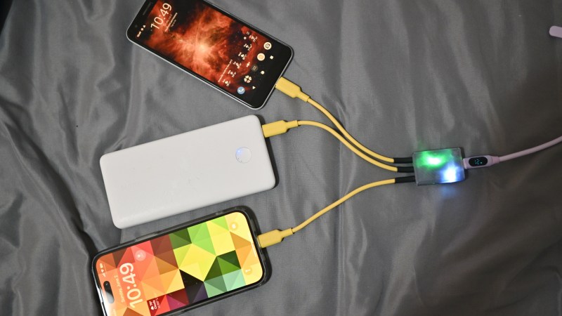
There’s no shortage of USB-C chargers in all sorts of configurations, but sometimes, you simply need a few more charging ports on the go, and you got a single one. Well then, check out [bluepylons]’s USB-C splitter, which takes a single USB-C 5V/3A port and splits it into three 5V/1A plugs, wonderful for charging a good few devices on the go!
This adapter does things right – it actually checks that 3A is provided, with just a comparator, and uses that to switch power to the three outputs, correctly signalling to the consumer devices that they may consume about 1A from the plugs. This hack’s documentation is super considerate – you get detailed instructions on how to reproduce it, every nuance you might want to keep in mind, and even different case options depending on whether you want to pot the case or instead use a thermal pad for a specific component which might have to dissipate some heat during operation!
This hack has been documented with notable care for whoever might want to walk the journey of building one for themselves, so if you ever need a splitter, this one is a wonderful weekend project you are sure to complete. Wonder what kind of project would be a polar opposite, but in all the best ways? Why, this 2kW USB-PD PSU, most certainly.


Honestly, what I want to see is a USB-PD data/power splitter. I want to be able to feed data and select the higher power on the same USB port for 3D printing toolheads. Then you can do something like universal changeable printheads with a single cable. I still do not think I’ve seen power and data on the same cable; maybe it’s a limitation of the PD spec that I am not understanding clearly.
You can absolutely do power and data on the same cable, that’s how every USB2 (and beyond) device works when you connect it with a C-C cable! The power is negotiated over the CC channel, so you can just use a device that splits off the CC pins – or the data pins.
The reason is the high power and high speed data cables cost a pretty penny. I think many of the reasonably powered cables 20-40w usually can do usb2 speeds (480mbps). Higher data speeds require more wires and highest of any reasonably length start requiring additional chips at the ends for error correction
No such thing as a 20W/40W cable, thankfully! That is only gas station cardboard box labelling nonsense (at least, that’s the only place I see it). Any C-C cable is capable of 60W (20V/3A), and you an easily find 100W cables that do 5A, they’re just a little more expensive. The downside is that you only get two signaling wires (D+ and D-), though; a USB3 cable might be more helpful with that. 480Mbps is the lowest speed a C-C cable will support, there aren’t any that support less, apart from data-less cables that are rare and not allowed by the standard.
f looking for higher wire count, you can often get USB3 cables with 4 more diffpairs in them, though unsure on 100W, but should be possible. Also, yeah, at some point (i.e. TB support) cables will start having chips inside them for high-speed signal conditioning, which might make single-ended signal passthrough a bit more complicated. Even with USB2 cables, though, can already do RS485!
This is a very timely article for a Framework laptop project I’m working on, and incredibly well-documented to boot, setting the bar for such things. The author could benefit from using the “Fabrication toolkit” plugin available for KiCad (through the built-in plugin manager), though, which would greatly simplify production of their BOM and production files — I had to hunt down the XLS file for the JLCPCB part numbers to yoink, instead of finding them in the schematic as I’d expect.
Anyway, well done!
While I’m giving out KiCad hints: https://github.com/uPesy/easyeda2kicad.py is a super-easy way to import parts sourced from LCSC, https://dfm.jlcpcb.com/ is surprisingly useful for finding fab issues that escape KiCad, and https://yaqwsx.github.io/jlcparts/ is a lifesaver for working around the limits of the broken JLCPCB part search system. And https://github.com/bennymeg/Fabrication-Toolkit is the github source for the fabrication toolkit I mentioned above, and https://github.com/cscott/ExternalEnclosureFW16 is the project I’m working on which I’m going to yoink the power switch from the OP’s project for.
Useful! I specifically charge my phone overnight with a 1A charger and a micro USB-> USB-C adapter.
THis is because the lower charge current is kinder to the battery, and it only needs 4 hours anyway.
ohhh I didn’t even think of that, and now I want such an adapter!
Erh What? If you connect D+ and D- together youll get the 3A. And then you can split it into one amp lines with resistors. When then voltage drops to 4.5V the client assumes the power supply cannot deliver more. Thus suitable resistor would be 0.5 Ohms. Or is there something else, which is beyond my limited comprehension.