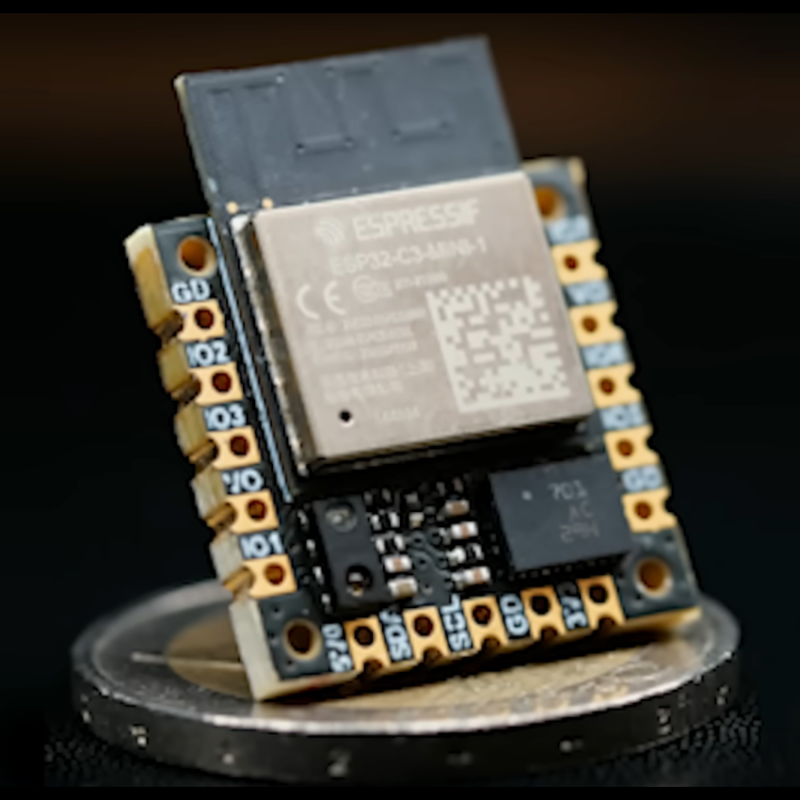
As things get smaller, we can fit more processing power into devices like robots to allow them to do more things or interact with their environment in new ways. If not, we can at least build them for less cost. But the design process can get exponentially more complicated when miniaturizing things. [Carl] wanted to build the smallest 9-axis robotic microcontroller with as many features as possible, and went through a number of design iterations to finally get to this extremely small robotics platform.
Although there are smaller wireless-enabled microcontrollers, [Carl] based this project around the popular ESP32 platform to allow it to be usable by a wider range of people. With that module taking up most of the top side of the PCB, he turned to the bottom to add the rest of the components for the platform. The first thing to add was a power management circuit, and after one iteration he settled on a circuit which can provide the board power from a battery or a USB cable, while also managing the battery’s charge. As for sensors, it has a light sensor and an optional 9-axis motion sensor, allowing for gesture sensing, proximity detection, and motion tracking.
Of course there were some compromises in this design to minimize the footprint, like placing the antenna near the USB-C charger and sacrificing some processing power compared to other development boards like the STM-32. But for the size and cost of components it’s hard to get so many features in such a small package. [Carl] is using it to build some pretty tiny robots so it suits his needs perfectly. In fact, it’s hard to find anything smaller that isn’t a bristlebot.


9 axis nothing. It is just basic IMU that pretty much any microcontroller can handle and make something useful out of it.
Exactly, it doesn’t pretent to be anything else right?
When one brings the word “robot” together with “9-axis” one expects we´re talking about DOF. So, the wording is misleading.
yeah! we need 12 axis, no 24 axis!! no 42 axis of course!!!1!1eleven11!!
btw, what is your point exactly?
i really like the fact he included tiny mounting holes. but two sided components is increasing the price of production. oh well, thats a small sacrifice for a smaller board.
It has 8 GPIO broken outout, each with PWM that could control a microservo. So, you could make a a 8DoF robot with it. I’d argue the DoF for the IMU is more relevant to the sensor+brain module.
In the title, is the robot or the brain tiny? :DDD
The tiny robot’s brain is tiny.
They said “Robot” and i was waiting for any mention of motor controllers…
Maybe better motors.
https://www.msn.com/en-us/money/markets/electric-motors-are-about-to-get-a-major-upgrade-thanks-to-benjamin-franklin/ar-AA1sx6EQ
So tiny! That’s smaller than some standalone 9DoF IMU breakouts! Now I wonder if it may make sense to put one at each actuator. Also, this can be useful for more than just robots.
It would be an interesting project to see if one could replace joint encoders with IMUs. It would likely be very difficult due to noise and vibration, but could drastically decrease cost relative to typical joint encoders.
Perhaps more realistically, it might allow for arm flex compensation.
It is well done, but really doubt how big the market for this is.. if you r building a robot you can spin the entire PCB yourself, it would still require a lot of engineering. If you make 7 euro’s per board. You have to sell A whole lot of these chips. Ideas I would think of are; energy monitor with esp 32 to measure energy consumption by industrial machines. A small tracking device if you want to track something or someone.. these things are still fairly expensive and or require subscription..
The robots he is controlling with his tiny board are small. I’ld like to see more on the motors and H-Bridge circuits he’s using on the smallest robot. Getting the micro-controller smaller is a great start to tiny bots.