Fair warning: watching this hybrid manufacturing method for gear teeth may result in an uncontrollable urge to buy a fiber laser cutter. Hackaday isn’t responsible for any financial difficulties that may result.
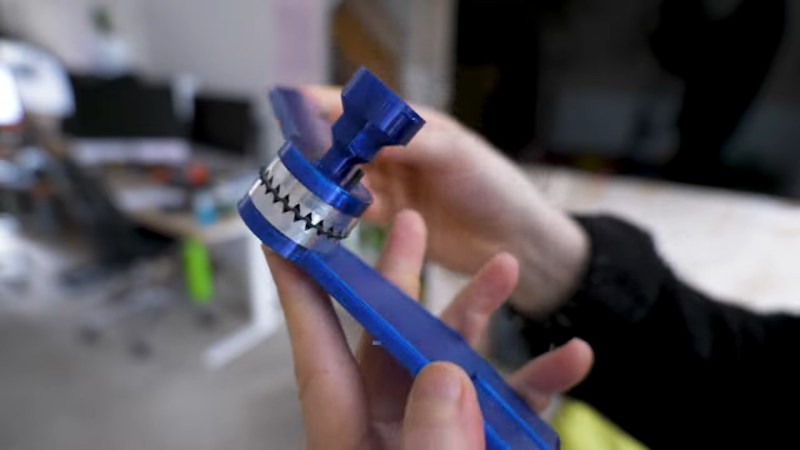
With that out of the way, this is an interesting look into how traditional machining and desktop manufacturing methods can combine to make parts easier than either method alone. The part that [Paul] is trying to make is called a Hirth coupling, a term that you might not be familiar with (we weren’t) but you’ve likely seen and used. They’re essentially flat surfaces with gear teeth cut into them allowing the two halves of the coupling to nest together and lock firmly in a variety of relative radial positions. They’re commonly used on camera gear like tripods for adjustable control handles and tilt heads, in which case they’re called rosettes.
To make his rosettes, [Paul] started with a block of aluminum on the lathe, where the basic cylindrical shape of the coupling was created. At this point, forming the teeth in the face of each coupling half with traditional machining methods would have been tricky, either using a dividing head on a milling machine or letting a CNC mill have at it. Instead, he fixtured each half of the coupling to the bed of his 100 W fiber laser cutter to cut the teeth. The resulting teeth would probably not be suitable for power transmission; the surface finish was a bit rough, and the tooth gullet was a little too rounded. But for a rosette, this was perfectly acceptable, and probably a lot faster to produce than the alternative.
In case you’re curious as to what [Paul] needs these joints for, it’s a tablet stand for his exercise machine. Sound familiar? That’s because we recently covered his attempts to beef up 3D prints with a metal endoskeleton for the same project.
Thanks to [Ziggi] for the tip.


Hirth couplings (joints) are indeed a quite nice invention. Probably patented once (just like the generic “crank shaft”, but long expired. And many people have seen these without knowing their name. These wavy lines appear on lots of objects. They find applications from bicycle cranks and lamp posts to very accurate. The best I know is in the Newbould model 202 spinning fixture (patent 3846912 from 1976) This fixture uses 3 stacked hirth couplings to sat angles very accurately. There are also some CNC machines with 3+2 axis which use a dual hirth joint to (automatically) set the angle of the main spindle to some known angle.
It’s nice to see this article about 3D (2 1/2D) laser etching. I guess it’s quite difficult to set the depth per layer, (and with that the slope of these teeth)
Which reminds me: Yesterday I bumped into a kickstarter for a laser welding aparatus. Nice piece of equipment, but also a bit scary, like “laser rifle, 40 watts range” (Heavy Arnold voice, leather jacket and sun glasses). And this thing is 700W laser output, and quite well focused.
https://www.kickstarter.com/projects/16159264/xlaser-the-ultimate-4-in-1-laser-welding-revolution
But for the Hirth joint. The one in the video is not properly made. It looks like he etched parallel V grooves in each of the halves. In a proper Hirth joint, all the lines must form pie charts, and come together in the center of the circle. It’s quite easy to find some papers with the math involved for Hirth joints.
Wild that someone managed to score a patent on what is essentially just two face gears meshing.
It was mentioned above, but in the late 1700’s someone got a patent for “the crank” on steam engines. James Watt and co had to come up with a more complicated geared mechanism to use on their earliest engines.
https://en.wikipedia.org/wiki/Sun_and_planet_gear
Albert Hirth was quite an amazing inventor
https://de.m.wikipedia.org/wiki/Albert_Hirth
It’s the details that were patented, after all the watchmaker it was originally developed for knew all about gears.
Hirth the company made high performance crankshafts with roller bearings ( think for a moment about getting roller bearings on a crankshaft ) that were used in racing cars back in the 1950s and early 60s before modern motor oils.
And as others have said, this isn’t really a hirth joint.
Similarly similar; Curvic couplings are often used for CNC lathe turret indexing
I’ve seen crown gears used for locating indexable tables as well (unclamp rise off gear, rotate, clamp settle on gear)
positioning is rather repeatable for such assemblies if done well
Shout out for naming the most ingenious use of divider teeth ever- the Newbould 202 indexer. If you Google it you will find the originator talking about how he invented it. He had the incredible honor while he was alive of being the only living person with a patent on something the patent office deemed a fundamental mechanism. I’m probably using the improper term, but things like wedges and pulleys. The very most basic fundaments of all mechanics. All of them had been invented thousands of years ago except for his!
A big gripe I have with the author and commenters- these ARE NOT GEAR TEETH. They do not rotate against each other to drive anything. These are a type of indexing tooth. Old rotary tables made by Moore corporation (of jig borer fame, look up the book Foundations Of Mechanical Accuracy by Moore, there really should be a featured article on Hackaday about this book because of how game changing it is for mechanics) used this type of serration on extreme precision rotary dividers, they did not continuously rotate the way people think of normal rotary tables.
They cut these and got hard indexes that were established by optical prisms for positional accuracy. The top half would lift straight up with a cam and the user would manually rotate the top and then it would lower and lock in place at an exact angle.
So these are not gear teeth, and I wish people would stop referring to them as such. They are a type of indexer tooth.
Other than that this is an extremely cool use of a fiber laser! I definitely want one.
That laser seems dangerous, it should be banned showing here.
This is what almost all fiber laser engravers look like, I have one, and they don’t use covers or closed cabinets, you just have to wear suitable laser goggles.
They do; you’re supposed to provide the cabinet.
Dangerous things are acceptable, you should be banned from posting here.
Word
Galvo fiber Laser engravers are relatively safe. Their beam calumniates in a relatively small space and after being reflected and scattered, the relative power density of the beam quickly decreases. The primary hazard isnt the beam, its the potential fumes and particulates generated during the engraving process.
Auto correct manual correction: collimates
man those teeth look like garbage…but, like it says, good enough for this purpose. i can sure imagine why you wouldn’t want to print that out of plastic. but then he whips out some sort of felt/rubber washer, and puts it between the two rings of teeth. i don’t think that would have occurred to me, but that’s what i would do…and with that washer there, for moderate loads, i’d be pretty confident to grip it with the kind of texture i can reliably print in plastic too.
so i learned something i’ll probably actually use thanks :)
Maybe knurling would produce enough of a texture to perform the same function, permitting one do the whole thing on the lathe.
Fiber laser ENGRAVER, not cutter. It might sound pedantic but theres a significant difference between these machines. One uses a galvanometer head and the other uses a focusing head and a gantry. Both surface finish and roundness are less the machines fault than the operator giving up at “good enough”. Although, precision surfacing benefits greatly from the more expensive 3d galvanometer option, the result with this (2.5D) system could have been greatly improved with a bit more trial and tuning,
Not sure if the two are really as separate as you imply – I’ve definitely seen things advertising themselves both ways so at least some of them by your definition would be incorrect. Seems to me like the names are mostly used to differentiate the power/cutting depth possible in a pass rather more than the method of moving the laser spot around.
many diode based laser systems advertise themselves as both engravers/cutters.
Ive never seen a Fiber laser engraver marketed as an engraver/cutter. Fiber laser engravers are usually in the 30-150W range. At those power levels they can only CUT thin plastic sheets. You can certainly engrave a line repeatedly and get a cut in relatively thin metal sheet but that capability is so limited that its not really a sell point for most manufacturers.
Fiber laser cutters are typically 1000W+. Fiber laser cutters below 500w are really only used in plastic cutting,
In any case, the system used here is not CUTTING, its engraving, because its a galvo based fiber laser engraver.
I have to push back on the way you define engraver vs cutter. Engraving and cutting are different process objectives that can both be accomplished using a variety of laser systems and a variety of motion control schemes. Whether you are using a laser to mark, etch, engrave, or cut – the intended process is not really dependent on how you move the laser’s beam around your substrate. You can accomplish any of those processes by moving the substrate around under the beam (“bed slinging”), by moving the entire laser head around via a gantry system, or by manipulating the beam path using mirrors that rotate (mirror galvanometer) or move position. Engraving vs cutting really has to do with how the laser beam interacts with the substrate, not how the laser/substrate moves around.
I would argue that defining a laser system as an engraver vs cutter would be more dependent on the laser’s power – a lower power system might be able to mark and engrave, but not have the power to cut through rigid substrates.
I realize that marketing departments have all but taken over even technical terminology. If you put aside how things are advertised and instead think about process/function, its easy to understand that your intended outcome on the substrate (engraving vs cutting) is not dependent on how the beam moves across the substrate.
Sorry if you dislike my words, I agree that engravers and cutters IN GENERAL are as you have said. However, FIBER laser engravers are galvo based, and FIBER laser cutters are gantry based. FIBER laser engravers are typically 30-150W sometimes as high as 300W. FIBER laser cutters are typically 1000W+ with the rare exception of an occassional 500W system being employed for thin plastic cutting.
Can you setup a gantry based fiber laser engraver without a galvo, sure why not. Good luck finding one manufactured as such. Big fiber laser engravers are typically hybrids with a gantry and a “flying galvo head”.
Can you cut with a galvo, sure. Thin stuff, mostly plastic or with many shallow passes. Galvos that can withstand high power (1000W+) exist but are VERY uncommon.
Tiy can throw hypotheticals and whatabouts around endlessly, TECHNICALLY you would be correct. The REALITY of the available devices on the market is as I originally stated when you are looking at FIBER laser systems.
And the system used here was not a Fiber laser cutter, nor was it cutting. It was a fiber laser ENGRAVER, and it was engraving.
Interesting coincidence. I spent most of last week doing research on Hirth joints.
As mentioned in the article above, camera gear is a very accessible source of high quality Hirth couplings if the size works for you. Standard seems to be 1.25″ (32ish mm) diameter with an M6 fastener in the middle.
Here’s a semi random example on Amazon for about $9 US.
https://www.amazon.com/CAMVATE-Rosette-Standard-Accessory-Diameter/dp/B072BX2QPY
Lower cost options available from the usual sources, under a dollar in some cases.
I was pleasantly surprised at how rigidly they lock up with surprisingly little torque on the bolt.
Hmm. I never thought of mounting a rotary table on a shaper before, but that sounds like a quick way to make these teeth.
From the title and lead picture, I was hoping to see a laser cutter head mounted on a lathe, with the beam cutting through the diameter of a piece of round stock.
That’s a clever combination of lathe and laser for cutting gear teeth! Using a laser for precision and a lathe for shaping seems like a great way to improve accuracy and efficiency. This could be a game-changer for custom gear production.
The combination of a lathe and laser is genius—gear cutting just got so much easier!