We’ve seen tons of projects lately using the ESP32-C3, and for good reason. The microcontroller has a lot to offer, and the current crop of tiny dev boards sporting it make adding a lot of compute power to even the smallest projects dead easy. Not so nice, though, is the poor WiFi performance of some of these boards, which [Peter Neufeld] addresses with this quick and easy antenna.
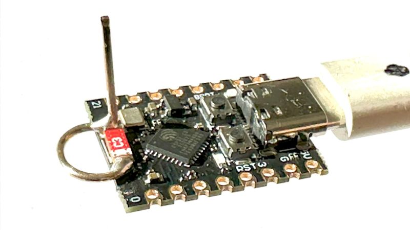
There are currently a lot of variations of the ESP32-C3 out there, sometimes available for a buck a piece from the usual suspects. Designs vary, but a lot of them seem to sport a CA-C03 ceramic chip antenna at one end of the board to save space. Unfortunately, the lack of free space around the antenna makes for poor RF performance. [Peter]’s solution is a simple antenna made from a 31-mm length of silver wire. One end of the wire is formed into a loop by wrapping it around a 5-mm drill bit and bending it perpendicular to the remaining tail. The loop is then opened up a bit so it can bridge the length of the ceramic chip antenna and then soldered across it. That’s all it takes to vastly improve performance as measured by [Peter]’s custom RSSI logger — anywhere from 6 to 10 dBm better. You don’t even need to remove the OEM antenna.
The video below, by [Circuit Helper], picks up on [Peter]’s work and puts several antenna variants to further testing. He gets similarly dramatic results, with 20 dBm improvement in some cases. He does note that the size of the antenna can be a detriment to a project that needs a really compact MCU and tries coiling up the antenna, with limited success. He also did a little testing to come up with an optimal length of 34 mm for the main element of the antenna.
There seems to be a lot of room for experimentation here. We wonder how mounting the antenna with the loop perpendicular to the board and the main element sticking out lengthwise would work. We’d love to hear about your experiments, so make sure to ping us with your findings.


Would replacing the onboard antenna with a pigtail work?
I’d have some more freedom to attach different antennae then.
The way I understand it, yes. If you remember the old PCB antennas, they would be as far isolated from the main PCB as the SMD antenna in the first board example. The same conclusion the article arrives at. The “minified at any cost” boards are simply “too busy”.
I worked for a testlab and the funny thing was we discovered at one time that the actual “antenna” was an ordinary zero-ohm resistor. Turned out that in the aplication note the recommended layout was the real antenna. Nice upcharge from 0.1 cents to a couple of bucks selling these.
A good external antenna will actually be the best solution. My intention was to make the mod as simple and effective as possible . In contrary to the video I compared a modified board with the original at the same time and location. The two graphs show the good results at https://peterneufeld.wordpress.com/2025/03/04/esp32-c3-supermini-antenna-modification/
There are always the Xiao offerings if you prefer an external antenna with your tiny board.
It seems to me, that if the problem is not having enough clear space around the antenna, the antenna could be removed from the PCB and mounted on short jumper wires (only need about 6 mm) off-board. This would take considerably less space than the antenna described in the article.
No, this SMD antenna is not an aktive component like an LED etc, which just needs DC supply. The jumper wires will become a radiating part of a very bad matched „jumper+SMD“ antenna.
The leakage radiation from the wires might well do better than the SMD antenna, simply because they are larger. Beating an antenna with a gain of -7dB or so by accident is easy.
My aim was to have a reproducible simple solution – ONE wire should be it! More at https://peterneufeld.wordpress.com/2025/03/04/esp32-c3-supermini-antenna-modification/
I’ve modded these boards to use a short SMA pigtail soldered to the feed and use the bottom of the adjacent capacitors for ground, removing the original antenna, and found that there’s not much gain over doing this mod or wiping off the antenna and using a 28-30mm piece of wire. The mod gives slightly better performance but a pigtail would give more flexibility in choosing more directional antennas or durable antennas. I use these for ESP-NOW transmitter sensor nodes and just wipe off the antenna and solder on a wire.
You are right about the better directivity of a straight wire.
But if you want the radiation pattern still to be omnidirectional AND the WIFI range increase , this angled wire with the loop is a very good choice.
You should consider that the ceramic patch is optimized for round shaped reception pattern, while the Lambda/4 has a direction in the vertical direction. if the basestation is in diraction of the Labda/4 wire it might get no signal. But inhouse you have a lot of reflections which help.
CA-C03: https://fcc.report/FCC-ID/2ASYE-T-DONGLE-S3/6952910.pdf
tl;dw, but It’d be interesting to see how far the chip antenna on that board is away from its design performance. Test setup really is nothing like the product scenario.
TRY :” QUANTUM CHIP ANTENNA” by ORBITAL RADIO RESEARCH . It’s a nano sized signal sucker.
http://www.orbitalradioresearch.com
From their website ….. ” It optimizes connectivity by modulating ambient light sources, achieving 100% signal coverage while minimizing noise and latency.” HUH? RF?
Sorry If I missed something.
Is it legal though? In most countries, you don’t need to have a radio operator license to operate and buy these kind of modules because they’re pre-tested for EMI compliance, radio spectrum and transmission power limits. If you modify them, they’re no longer in spec and you can fall foul with whatever radio regulations you have.
The ones from AliExpress with the faulty antenna are not the tested compliant units you’re thinking off.
Ordering these unknown parts from AliExpress makes you the importer and responsible for ensuring compliance.
The low price super mini is not approved.
There is a version of super mini with CE FCC with shield can and the seperate flex antenna much like the regular wrover module.
Cost $23 typically
You mean “Wroom” Modules and they cost the same as the super mini
You can always certify yourself ($$$), but in the US, to have the benefit of modular approval, you should only use the ones with a metallic shield (if you want to sell these products.)
For the EU you have to stick to the certified antenna gain to reuse module reports, otherwise you again need to certify yourself.
I do not understand why they keep the original antenna on. If you are going to use a quarter wave antenna, better just remove the original completely. The extra loop is not really needed, but is good for mechanical support and ESD protection, also filters some of the low-band spurious products.
Also claims of incredible gains should always be taken with a grain of salt. Although you can loose a couple of dB’s with wrong placement, you really have to try hard loosing 10 dB. In the end it is mainly mismatch loss that causes loss of energy.
The actual gain(directivity) of the antenna can also not be increased with a small antenna. To achieve gain you need a physically large antenna. And even then, antenna gain is only beneficial is one specific direction. All other directions will have lower performance. Think of it as a balloon. If you squeeze it in one direction, other directions will increase. It all boils down to conservation of energy. In specific these chip antenna’s are optimized to show isotropic performance. At least better than a dipole.
The point is that the SMD antennas on these mini boards are not positioned according to the datasheet. The mismatch is so significant that it causes the chip to heat up.
The new antenna wire forms a quarter-wave antenna, with the loop and straight part ensuring an omnidirectional radiation pattern. The original blog post is cautious about claiming gains of more than 6 dB, but the measured improvement compares a modified module to an original one mounted next to each other, both connected to a distant access point at the same time.
$350 each for FCC and CE in Shenzhen if they have the docs and setings from the manufacturer.
Do not bother wasting money on these. Better throw it away immediately. For the EU, no way you can get proper test reports for at least EN 301 489-1, EN 301 489-17, EN 62368-1, EN 300 328, EN 62479.
For the US, the FCC certification fee is already higher, not even taking into account testing.
In the standards mentioned, I already assumed you want reduced output power. If you want full power, assuming it is within limits, you might even need to go for the very expensive EN 62311.
The answer you going to find for these kinds of videos is always “no, but who cares?”
I didn’t spend a whole 22mins of my life on that talking head video, but it appears that he would benefit from learning a little bit of antenna theory and practice. Capacitive and inductive loaded antennas are always interesting.
I’d look at either any of the ARRL yearbooks, or at Thomas Lee’s Planar Microwave Engineering. The latter has a similar flavour to TAoE, including some delightfully droll observations.
The video misinterprets the correct and crucial length of the additional antenna wire. The total length, including both the loop and the straight part, is 31 mm.
This antenna is indeed a very simple but effective mod. Please be careful about the misunderstood dimensions in the mentioned Youtube video. The Wire is 31 mm in total – not more than! An the special combination of loop and straight part has a good reason too as you can see at my blog https://peterneufeld.wordpress.com/2025/03/04/esp32-c3-supermini-antenna-modification/
Not 6 or 20 dBm better. It may be 6-20 dB better. dBm is a power unit, dB is a dimension-less factor.
In fact 20 dBm would sounds more believable, based on nominal 20 dBm output power (100 mW), than 20 dBm more (+100 mW) would in fact be 3 dB more (2 x). It is way more believable than 20 dB more (100x).
Besides that, I would not be surprised that a this difference in power is due to polarization effects. The polarization is also rotated 90 degrees.
No, the new antenna has TWO parts exactly to produce both polarizations and to be omnidirectiona.
A quarter of the wavelength of a 2.4 GHz signal is approximately 3.12cm
https://www.whwireless.com/blog/principle-and-calculation-of-quarter-wavelength-antennas_b53
34 or 31 mm is all the same for the antenna radiating performance itself. The main thing is that you tweak the mismatch loss/VSWR interaction. (absolute gain vs realized gain). By making the antenna slightly shorter/longer it becomes slightly more inductive/capacitive, compensating the output impedance of the board. Also the antenna does not have a well defined groundplane, so will not be perfectly 75 ohms. I did not look it up, but the output impedance is probably more like 50 ohms.
Velocity factor, etc.
Make it a bit longer than you think you need, trim with a pair of wire cutters until you get it right.
(Then trim a little bit more, because you didn’t know it was right, and then re-do it from the start again, using measurements from the previous attempt.)
This alone will not help. You are doing the same mistake Youtube-Video showed. You end up with a well matched 5/8lambda antenna wire, BUT WITH A DONUT-LIKE RADIATION PATTERN. If you need/want this , ok . If you want to have an omnidirectional radiation pattern , stay at an angled 1/4lambda wire with 32mm total wire length.
does xaio esp32 os use debian?
AI Overview.
No, the XIAO ESP32 (and other ESP32-based boards) do not use Debian
as their operating system. They typically run a real-time operating system (RTOS)
called ESP-IDF (Espressif IoT Development Framework).
Why do you post ai replies to questions nobody asked?
It’s fascinating to observe what happens when a chain of people passes a piece of reasonable technical information from one mouth to the next ear, and so on. By the time the message reaches the last person, the technical output often has almost nothing to do with the original input.
My original blog post traveled via a YouTube video to Hackaday (HAD), and then to other valued eyes and fingers…
Oh OH OH!!
Did anyone read the original blog post at all?
Yes, almost everybody did.
You can tell by the lack of a large number of stupid responses ;-)
I don’t know anything about antennas but shouldn’t you remove the old antenna, since it has quite high (dielectric) loss?
Definitely. At least if the OEM tried to properly impedance match the chip antenna. Which is highly doubtful.
The SMD antenna didn’t have any loss – it simply didn’t radiate energy well because it wasn’t electrically well-tuned.
Now, this inductor is bridged by a 1/8 lambda section of a well-radiating 1/4 lambda antenna element.
If you were an oscillating electron – wouldn’t you take THAT path?
A got a bunch of these. You can get them barely working by reducing the power. I put them in the bin eventually. The Xaoi is a similar size and way better for the more expensive price, where ‘better’, means actually working. The most annoying thing is these are still for sale at all. People should buy them get refunds until they won’t be made and sold anymore.
On all of the S3 supermini that I have, the antenna is installed backward, so this mod works even better (due to the actual antenna not being connected to anything at all. Note that the feed in point for the antenna is on the side with the white bar, and the other side is just a mounting point. The S3 board has the feed trace going to the not-connected pad on the antenna :/ Using this mod without moving the antenna brought my RSSI up from -98dBm to -75dBm at 15m, which is still terrible but actually usable.
Die S3 Antenne ist oft eine RAINSUN antenne. Bei diesem Chip ist das nicht durch einen Punkt markierte Ende elektrisch nicht mit der Antenne verbunden, sondern nur ein mechanischer Befestigungspunkt. Die Originale Antenne ist also elektrisch gar nicht angeschlossen!
Wenn diese antenne mit der Schleife verbunden wird, wird sie nicht kurzgeschlossen, sondern hängt als zusätzliches strahlendes Element, an der Schleife, was zu einer vollkommen anderen unerwünschten Form führt.
The S3 antenna is often a RAINSUN antenna. In this chip, the end not marked by a point is not electrically connected to the antenna, but is only a mechanical attachment point. The original antenna is not electrically connected at all!
When this antenna is connected to the wire loop, it is not short-circuited, but hangs as an additional radiant element, on the loop, which leads to a completely different unwanted shape.
Remove the SUNRAIN antenna and turn it around or excahnge it by the described wire wire