Sometimes you see a project and immediately, before going into the details, your mind throws up the old refrain: “coulda used a 555” — well, [Hulk] actually agrees when it comes to his ESP32-based, 3D printed roulette wheel. The first version did use a 555, but then feature creep kicked in and the final project ended up with an ESP32 instead. We’ve all been there.
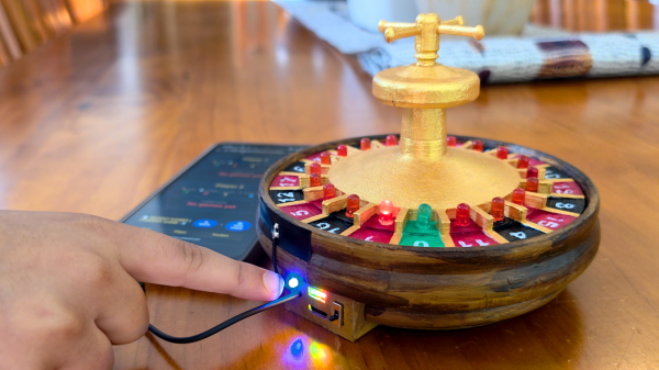
The roulette wheel circuit is retained from the 555 version, with the ESP32 providing clock pulses instead of the venerable oscillator chip — it uses a pair of decade counters to create the chase effect of the LED around the wheel. With a handsome printed enclosure, [Hulk] could have stopped there, but then he’d have to keep track of scoring and the like manually like some kind of dark age peasant. It’s the 21st century, we have computers to to that for us!
Now, even though the ESP32 is still driving the LED chase via the decade counters, it can keep track of where the “ball” of light lands, and reports that via WiFi or serial. While it would have been an option to run the whole game on the ESP32. [Hulk] just has those values put into an SQL database on a server, which also runs the game front-end via PHP. The resulting web page lets two players make their bets and track their wins and losses over time. You can see that in action in the video embedded below.
Overkill? Sure, but we suspect [Hulk] already had the equipment and experience to make this the fastest way to get a playable game. There are easy ways to serve web content from an ESP32, but the easiest tool to use is always the one in your back pocket, right?
Continue reading “ESP32-driven Roulette Wheel Could Have Used A 555, But That Didn’t Have WiFi”