It’s an unfortunate fact that when a scientist at MIT describes an exciting new piece of hardware as “low-cost,” it might not mean the same thing as if a hobbyist had said it. [Caden Kraft] encountered this disparity when he was building a SCARA arm and needed good actuators. An actuator like those on MIT’s Mini Cheetah would have been ideal, but they cost about $300. Instead, [Caden] designed his own actuator, much cheaper but still with excellent performance.
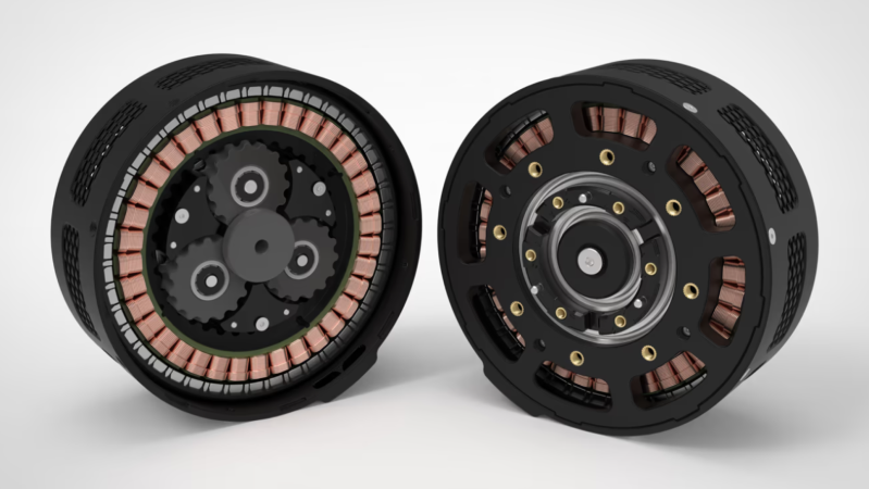
The actuator [Caden] built is a quasi-direct-drive actuator, which combines a brushless DC motor with an integrated gearbox in a small, efficient package. [Caden] wanted all of the custom parts in the motor to be 3D printed, so a backing iron for the permanent magnets was out of the question. Instead, he arranged the magnets to form a Halbach array; according to his simulations, this gave almost identical performance to a motor with a backing iron. As a side benefit, this reduced the inertia of the rotor and let it reverse more easily.
To increase torque, [Caden] used a planetary gearbox with cycloidal gear profiles, which may be the stars of the show here. These reduced backlash, decreased stress concentration on the teeth, and were easier to 3D print. He found a Python program to generate planetary gearbox designs, but ended up creating a fork with the ability to export 3D files. The motor’s stator was commercially-bought and hand-wound, and the finished drive integrates a cheap embedded motor controller.
To test the actuator, [Caden] attached an arm and applied perpendicular force. The actuator only failed on the first test because it was drawing more current than his power supply could provide, so he tested again with an EV battery module. This time, it provided 29.4 Nm of torque, almost three times his initial goal, without suffering any damage. [Caden] only stopped the test because it was drawing 50 A, and he thought he was getting close to the hardware’s limit. Given that he was able to build the entire actuator for less than $80, we think he’s well exceeded his goals.
If you’re interested in the inspiration for this actuator, we’ve covered the Mini Cheetah before. We’ve also seen these drives used to build other quadrupedal robots.
Thanks to [Delilah] for the tip!


This isn’t hacking anymore, this is just a great example of good engineering on a budget by a talented and passionate individual. Very impressive and kudos for contributing the work to the public domain!
Absolutely spot on.
Not hacking, competent engineering.
Oh yes they have. The reason for the involute gear profile is that the pressure point between the teeth and the forces follow the tangent of both gears throughout the rotation, which means both gears roll at a constant speed.
With the lobed shape one of your gears will be rolling faster and slower as it meshes with the other, producing noise and vibration, because the velocity ratio between the two gears changes as the teeth roll. You can hear it from the test videos, how “crunchy” the gears sound when moving rapidly. That means they won’t have a very long life in use, and counting the motor revolutions won’t give you a precise estimate of movement.
Not to mention what happens when you turn such a gear into a herringbone gear.
Each cross-section of the gears represents a gear-pair in a different phase of meshing, and therefore a slightly different gear ratio for the pair since that is changing cyclically through the rotation.
What happens when you have two gear pairs with slightly different ratios on the same shafts trying to turn at the same speed? They don’t mesh properly and they’ll jam.
What happens in practice for the double helical gear is that the gears grind each other and force the plastic to conform until they develop enough slop that they can agree on a mutual speed.
My own guess is that building the whole thing out of metly 3D printer plastic is going to be the larger problem.
Didn’t they use a cycloidal gear which should also have a constant rotation speed?
Correct, they’re not involute gears.
Yes, so? I’m not sure what you’re saying?
Involute gears are not the only kind of gears that can keep the angular velocity ratio constant, others also obey the fundamental law of gearing.
Involute gears are standard not because they’re the only profile that maintains constant ratio (they aren’t) , but because they also have a lot of other benefits when making them with traditional machining techniques. If you’re not using traditional machining, then other profiles may in fact be superior.
The fundamental law of gearing with cycloidal gears only holds at one exact center distance of the gears, which is not easily met with practical manufacturing and assembling tolerances. While in theory you can design a cycloidal gear pair that produces a constant velocity ratio, the more you get it wrong in manufacturing, the less constant the velocity ratio will be, which is to say it will always be a little bit off.
The center distance also varies with vibrations and material strain under load, which then induces more vibrations as the gears turn. Involute gears turn a lot smoother because of this:
https://www.tec-science.com/mechanical-power-transmission/involute-gear/meshing-line-action-contact-pitch-circle-law/
“the transmission ratio of involute gears is independent of the center distance (for example, this is not the case with cycloidal gears).”
Involute gears can be mixed and matched, while cycloidal gears always have to be made as a fitted pair. This can present problems if you need to have more than one gear in contact.
And you don’t have to make involute gears with sharp corners either. It’s just a result of how most involute gears are made.
Which was my entire point. If you’re 3d printing them anyway, stuff like “always have to be made as a fitted pair” becomes completely irrelevant. Each gear can be completely custom just as easily as if they were all uniform – there’s no tooling required.
If you have a planetary gearbox with one sun gear, three planet gears, and one ring gear, can you fit all the gears together while accounting for manufacturing tolerances making each gear slightly different from how you designed it?
Also note that the cycloidal gears may start as a fitted pair, and you may print multiples to select the pair that happens to match each other despite variations, but they won’t remain that way with wear and deformation under load.
What is the repeatability of 3D printing anyways?
I’m glad other’s mentioned the problems with moving away from involute gears, because that’s what immediately leapt into my mind. You can stick with involute gears and tweak them away from the standard 20deg pressure angle to make them more 3D printable while also getting some other benefits. I stumbled on https://www.geartechnology.com/low-loss-gears which had some very interesting and counter-to-conventional-wisdom results for high efficiency gears that also happen to work well with 3DPrinting that include;
Use high pressure-angles like 40deg. This makes the tooth more rounded and strong.
Use a very low transverse contact ratio like 0.6. This means you can shorten the tooth and chamfer the tips and roots making them more rounded and strong.
Use a wider tooth face and higher helix angle for a high axial contact ratio. This brings the total contact ratio back up above the minimum recommended 1.2 and spreads the load over more teeth.
The increased rounding and shorter teeth make these easier to 3DPrint, and 3DPrinting makes helical (and particularly herringbone) gears much easier to make than traditional machining. It’s an added bonus that these all add up to significantly more efficient gears under normal operating loads/speeds too.
The only other point worth mentioning is for this particular use-case it is a super-low Kv motor with very low RPM, at least compared to most BLDC motors, so the lack of constant ratio with the non-involute gears might be barely noticeable. Also the “jamming” effect from using them in helical gears would translate into low backlash (after they wear in enough to work), which probably matters more than efficiency for this application.
“DC” ahh so we’re not trying to break any durability or efficiency records here..
How would “DC” reduce durability or efficiency?
care to elaborate? I was under the impression that BLDC motors were rather on the efficient side.
Apparently, permanent magnet synchronous motors can be more efficient, at least according to a recent Great Scott YouTube video.
What, exactly, is the difference between a permanent magnet synchronous motor and a brushless DC motor (which is synchronous and uses a permanent magnet)?
And don’t say “watch the video”. That handwaving and woo about waveforms doesn’t say squat.
The control scheme.
A bog standard BLDC motor just replaces the mechanical commutator with Hall-sensor switches to mimic the operation of a standard brushed DC motor, while the PMSM motor employs more elaborate control schemes like FOC. It’s rather that the concept of the BLDC got “upgraded” over time to the point that these two are now identical.
Or, from the application’s point of view:
A BLDC motor is controlled by a DC voltage (e.g. PWM) and it responds by generating a back-EMF just like a brushed DC motor. The actual switching is done solely by the position of the rotor and it is almost always fixed.
A PMSM motor is controlled by an AC variable frequency drive, and it responds by generating an A/B tachometer signal or a three phase hall-sensor signal, or you’re measuring the phase current of each three phases to calculate the field orientation.
When people augment brushless motors with current sensing and velocity/phase feedback to run more advanced control schemes, they are creating PMSM motors, but they still keep calling them BLDC motors out of habit.
So, the industrial “BLDC” motors I’ve been using for the last 18 years are actually PMSMs now. OK. Got it. I’ll adopt the newspeak immediately.
Internally, they’re 3-phase motors with hall effect position sensors, with encoders (optical, magnetic or RVDTs). As the application, I see the motor position in encoder counts (or microns). I tell the drive the desired motion profile, and it handles the details.
Over the decades the performance has increased, and communications migrated to ethernet from various serial protocols, and the drives have got smarter (particularly with tuning), but the underlying motor has not changed.
For the very largest industrial motors, there is still a difference, because you might not have a VFD in the loop and instead just run the motor directly off the grid, or you have a VFD but no direct feedback from sensors so you’re kinda running the motor up and down slowly to avoid slipping. This is fine for things like blowers or conveyor belts that either don’t have much load and require a steady speed, or the load is constant.
In those cases where the PMSM motor is running directly off of AC, there is a smaller induction motor in there that’s responsible for dragging it up to speed. Once the motor reaches synchronous speed the induction motor ceases to have an effect as the rotor is spinning without slip.
It’s like two ends of a spectrum. In the middle they blend in to each other.
Oops. Thanks for pointing that out; I’ve corrected it.
The original cheetah machines made 30Nm out of 850 grams and were probably 20% cobalt. A 6:1 planetary gearbox brought the output to 180Nm. They were slightly more expensive.