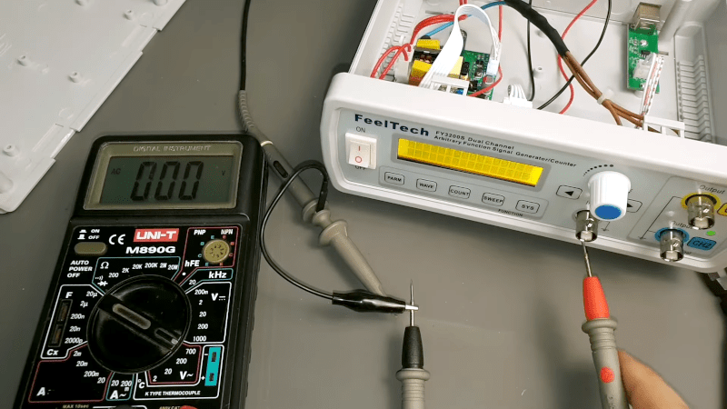
[CreativeLab] bought a cheap arbitrary waveform generator and noted that it only had a two-pin power cord. That has its ups and downs. We feel certain the intent was to isolate the internal switching power supply to prevent ground loops through the scope probes or the USB connector. However, it is nice to have all your equipment referencing the same ground. [CreativeLab] agrees, so he decided to do something about it.
Opening the box revealed that there was hardly anything inside. The main board was behind the front panel. There was also the power supply and a USB board. Plus lots of empty space. Some argue the case is made too large to be deceptive, but we prefer to think it was to give you a generous front panel to use. Maybe.
It was a simple matter to ground everything to a new three-pin connector, but that left the problem of the USB port. Luckily, since it was already out on its own board, it was easy to wire in an isolator.
Honestly? We’d have hesitated to do this unless we had made absolutely sure it didn’t pose some safety hazard to “jump over” the switching power supply. They are often isolated for some reason. However, the likelihood is that it is just fine. What do you think? Let us know in the comments.
A similar unit had a reverse engineering project featured on Hackaday many years ago. While these used to be exotic gear, if you don’t mind some limitations, it is very easy to roll your own these days.


Huh. So… how much current flows into the earth pin?
Sometimes, too much. Which is why your microwave has an earth pin. On this world (signal gens, scopes, and other test gear), ideally none at DC, and controlled at signal frequencies.
EArthing the signal ground is a many edged sword. You can float an unearthed output or input, but an unearthed output or input can float, which can reduce noise immunity.
An earthed signal ground can lead to shorts to earth, bu with appropriate protection (GFCI), this can protect equipment from some typed of shorts.
Many other edges here, including loading at frequency, max allowable ground float, and so on..
Hmm, OTOH discharging 1nF of parasitic capacitance at 100V is not going to be funny if ground is not mated first anyway. Regardless of how fast it builds up.
First of all using blue and brown cables for earth wires is not a good idea, better to use a yellow/green wire to see that is an earth conductor. Now If it’s necessary yo have a ground reference, it’s better to have a ground post and ise it to have a ground reference.
If the SMPS has a capacitive coupling between mains and the rest of the circuit and tis is a concern, maybe adding an insulting trasformer wit a electrostatic shiel between primary and secondary it’s a better idea.
First, I consider this a quite bad video. @01:19 you get a glimpse of the power supply and there seems to be an RF suppression / filtering cap in the lower left corner of the power supply (Next to the transformer, there is even an isolation cutout under (or near) it.
Hackaday’s concern about a “safety hazard to jump over the switching power supply is groundless . :) The Protective Earth terminal is meant to do exactly this: connect the metal parts of a case to GND.
You don’t get a high quality power supply in a function generator in this price range, but apart from the overall quality of this thing, the leakage is normal. It’s not a safety concern for humans, as the current is very low, a handful of uA. This power supply does have input filtering and some electronics on the secondary side, I’ve seen much worse then this, but there is not enough info to judge whether that power supply is of decent enough quality to be safe. Chinese standards are not very high in this regard (Or they are not checked very thoroughly).
When I sit on my chair and touch the tip of my scope probe, I can also see 100V on my Siglent scope. It’s just picked up from the mains wiring all over the house. This is all perfectly normal and harmless to humans, but I do agree that this leakage can damage electronics. You get a similar situation if the PE (GND) pin of your scope is not connected properly (Some of the mains sockets here in the EU accept plugs with PE, but the wall sockets do not have the PE). In that case you can feel a tingling when you touch the metal PC case. It can even be strong enough to hurt a bit, but as long as there are no real faults in the power supply, then it’s still just earth leakage from the input EMI filter and harmless (for humans).
It’s also quite common to modify these function generators and put in a low frequency mains transformer with linear power supply. This has much lower leakage. Usually good enough to keep the whole box floating without an PE connection, and that has it’s advantages too. Always having your function generator grounded is not really ideal.
I will stick with my 45 year old HP…..
Plastic… YUCH!!
Well, this reminds me a (not so) nice episode of my ancient life : The building where we worked was in two parts… each one with its own power circuit. The more recent was a standard 220V (yes french and EU standard). The other one was in fact on a 110 V power circuit, but “modernized” to 220 V using two 110 V lines in opposites phases… with the ground on the mid point.
Now introduce some computer (a VAX 780), a bit of network, a remote Ethernet to serial server and some VT200 terminals. The VAX and the terminal server was on the ancient power line, but we needed to install some terminals in the new building. It was not too far (15-20 m), so we estimated that a well shielded RS232 serial line will be enough.
After a terminal servers and two VT220 returned to Digital Equipment for being ineffective out of the box, we started to wonder if something else could be the cause.
After a week of head scratching (and another terminal server + VT220 blown up), we discovered that the serial line shield was connected on both side, hence connecting two grounds with a 110 V between them.
Since that time, I never look at two “ground” contacts the same way…
This is why “Ground” and “PE” (Protective Earth) are two separate things. Normally the GND wire and the PE wire are connected to each other (On the utility side, before the ELCB (Earth Leagage Circuit Breaker). The shielding of the RS232 cable should never have been connected to “GND” in the first place, but only to PE.
Also here in Europe (most) mains voltage plugs are not polarized. We do not really distinguish between “GND” and “Live” in single phase systems, but consider both wires “live”. This reduces the opportunity for mistakes between GND and PE by a lot. In houses the wires have defined colors Blue for GND, brown for live, black for “switching” and Green/Yellow for PE) but those wires are normally not visible by users. On a wall plug, you can not see which pin is “neutral” or “live”.
Also, every now and then I see electronic schematics where the PE symbol is used as a generic GND for a circuit. Please don’t do that. Use the GND symbol instead for your low voltage uC circuit.
To your last comment about PE and signal ground notation: which symbol do you use for which typically? I’m used to seeing the generic 3 line ⏚ for everything, with additional notation if it’s not chassis/earth ground. I’m aware of the crooked fork ground symbol, but it’s not obvious to me what you’d expect as signal vs PE ground.
i’m pretty sure i wouldn’t want this mod! My siglent oscope’s ground appears to be referenced to earth, and that isn’t a win for me. 90% of the time, it works out fine. But i guess sometimes i use un-isolated power supplies, and sometimes in order to make the most of two channel scope, I’m inclined to hook my scope’s “ground” probe to an in-between voltage instead of to the power-supply’s gound. Or even to two separate references for the two channels. And when i do that, the scope makes an awful noise and i disconnect it in a hurry and then i have to test whether i fried it. i think that’s happened 3x so far and each time it has not fried the scope and i have been able to figure out another way to make the measurement (or to live without it).
i don’t really know the ups and downs of it. i halfway hope for someone to tell me there’s an option in the scopes menus to change this behavior! But i generally wish the scope was isolated. Being isolated is the one advantage i can point to of the old battery-powered scope that i used to have (and which was otherwise infuriating to use). If i had an isolated power supply that i wanted to ground-reference, i’d just run an external ground connection (jumper wire) so i can enable/disable this hack. Which is apparently basically what would happen if i happened to hook my scope up to any circuit coming off of this signal generator anyways.
On nearly all scopes the BNC connectors are connected to the PE pin of the mains entry in a very similar way as the “hack” in this function generator. And this is done with thick wire too. Goal is that it can pass enough current to blow the mains fuses without damage to the scope. I’m mildly surprised it did not trigger your GFI (I guess the same as ELCB), but not everybody has those things. (But I do recommend to install one in the mains wiring to your electronics lab).
And this is indeed a limitation of common scopes. If your scope does not state very clearly that it has floating inputs, then you can be pretty sure that the BNC’s are connected to PE (And I assume you have some electronic knowledge, so you can measure the resistance to the BNC shell and the PE pin).
One of the possible remedies is to make sure that the gadget you are measuring is floating. This is one of the main uses of isolation transformers. Low voltage circuits are usually also floating relative to the mains voltage. Lab power supplies sometimes have an extra PE Banana / Screw connector near the output so you can choose whether the output is floating or mains PE / (GND) referenced.
Another option is to use differential probes for your oscilloscope. In that case you don’t have to connect the scope “GND”. You can also attempt to use two scope channels and then subtract them from each other (a common scope function). This creates a “poor man’s differential probe”.
Yeah, that sounds about right. I wonder why the GFI didn’t blow too…probably should test it. I imagined that the buzzing sound indicated i was triggering a protection circuit within the scope, rather than just dumping to earth. And thanks for the keyword ‘differential probe’ — of course there’s all kinds of probes i never thought of!
For many decades it’s been standard practice for electrical engineers to float a ‘scope by plugging the power into a 3 prong to 2 prong adapter. There’s some danger involved because metal parts of the ‘scope may be at a dangerous voltage, but that’s a known risk that comes with the job.
Occasionally I’ve heard the warning “If you work alone keep one hand in your pocket.”
“However, it is nice to have all your equipment referencing the same ground.” Maybe if every device is plugged into the same junction box. Decades ago, in the US, I routinely set-up or debugged advanced physics lab setups and the “grounds” were always a problem that required digging into all the instruments and power supplies and extra circuitry to know what was happening inside.
The best result was always isolated / 2-wire mains equipment, a single point common reference, shielded cables referenced at one end with the end chosen wisely, and metal enclosures for everything with the whole setup floating, as if using batteries, and some times with the whole rig shielded
One year we had 6 new Tek low cost CRT type scopes with plastic housings, several of them quit with a “POP!” during labs. Inside there is a braided “ground strap” from the front panel BNC commons to the “ground” pin on the power connector. Or I should say WAS a strap. There was no fuse involved unless the braid was considered a fuse.
Anyway, as a setup was assembled we checked for any unexpected currents or unexpected potentials exposed to touch. Instrument combos could have photomultiplier supplies, very big electromagnets, slow sawtooth generators of hundreds of volts, etc. side by side with pico-amp or femto-amp electrometers and photon counters, and stuff like that.
I used a book back then called “Grounding and Shielding Techniques in Instrumentation” by Ralf Morrison.
Long ago I was working on a pants-on-fire debug of a server DDR4 fault that necessitated the CPU vendor bringing onsite a large team and test gear worth costing more than a nice house in SF.
After the better part of a week, the lead engineer from the CPU company suggested our memory IO rail supply was unstable. Their reasoning was that they saw common mode glitching and dull edges on all the digital signals they were monitoring on the DDR bus. This would come and go every few hours or so.
We wanted to see proof. We didn’t see anything unusual at first, but by sheer luck I noticed out of the corner of my eye the person driving the JTAG debugger from their laptop plugging it in to charge. At that moment we saw the glitches on the scope.
It turns out the system under test was on its own 208V circuit while the scope, logic analyzer, and the laptop charger were on a power strip on a separate 120V power strip. They didn’t attach the grounds between the system board and the differential probes on the 13GHz scope, causing the probe’s amp to rail out from the ground loop offset between the system and the scope ground by way of the laptop charger and the JTAG adapter. The dull edges in the signals were from induced 60hz mains affecting the rail out of the probe relative to the signal.
The root cause of the bug wasn’t either company’s fault. The DIMM vendor got a large batch of faulty buffer ICs, and the buffer manufacturer footed the bill for the field replacement campaign.
Had a similar situation it was Embarrassing.
As a Tech / Engineer Know where your Ground Is….
Back to work on my AF-67
There has been a lengthy discussion and solutions to this problem in https://www.youtube.com/watch?v=pQxHFGXHPXg 7 years ago already.
At 4:34 in the video he added a jumper in the ‘D4’ position. Immediately below that are two side-by-side half-circle pads; their whole job in life is to accept a solder bridge which would connect those same D4 pads. I just noted it as an interesting oversight.
I have one of these function generators, honestly for the money it’s hard to fault it – I just needed something I could load a particular waveform into and this allowed me to do that with a USB-serial converter and a few lines of python.
It’s definitely not lab-grade but neither is the price. More than good enough for the average hobbyist.
Connecting the device’s ground to the mains ground ? Really ? This is sick and dangerous ! A much better idea is to remove that dangerous built-in SMPS converter and replace it with a transformer-based power supply with linear regulators 7812 (+12V), 7912 (-12V), and 7805 (+5V). This provides galvanic isolation from the mains and clean supply voltages. There’s plenty of space inside this enclosure.
Good Idea!
Better yet run that generator on a battery.
Problem Solved.
Now back to working on my AF-67…..