At some point during our primary school careers, most of us probably constructed a simple compass, often by floating a magnetized needle on a cork in a cup of water. The water in such a configuration not only lets the needle spin without friction, but also dampens out (so to speak) the needle’s tendency to swing back and forth across the north-south line. Liquid-filled compasses use the same principle, but even well-made compasses can develop bubbles when exposed to temperature or pressure variations. Rather than accept this unsightly state of affairs, [The Map Reading Company] designed a new kind of liquid-free, inductively-damped compass.
It’s hard to design a compass that settles quickly, even if it uses a strong magnet, because the Earth’s own magnetic field is just so weak, and the stronger the internal magnet is, the more likely it is to be thrown off by nearby magnetic objects. As a result, they tend to swing, overshoot, and oscillate around their final orientation for some time. Most compasses use liquid to damp this, but a few, mostly military compasses, use a conductive baseplate instead: as the magnet moves, it induces eddy currents in the baseplate, which create a weak magnetic field opposing its motion, slowing the magnet down. Inductively-damped compasses don’t get bubbles, but they don’t let you see a map through the baseplate. [The Map Reading Company] dealt with this by making the baseplate transparent and surrounding the compass needle with a ring of high-conductivity copper alloy. This gave him a clear baseplate compass for easy map reading which would never develop bubbles. It’s a simple hack, and should be easy to replicate, but it still seems to be a new design. In fact, [The Map Reading Company] is releasing most of the design to the public domain. Anyone can build this design.
If this prompts your interest in compasses, check out the Earth inductor compass. We’ve also seen a visualization of the eddy currents that damp these oscillations, and even seen them used to drive a bike.
Thanks to [Mel] for the tip!


I enjoyed the video, but I’m having a hard time comprehending how this can be a new invention. If compasses were already damped with conductive base plates, and a transparent base was desired, trying a conductive perimeter ring would have been pretty obvious to nearly any electrical engineer.
And yet it hadn’t been done
I guess not many electrical engineers are employed by compass manufacturers… lol
It’s industry. There’s so many small super easy wildly useful or at least somewhat useful things that don’t become products. Here’s a few reasons why I’ve seen good ideas/prototypes get squandered
-too new for the public
– unsure if there is a market
-cost
– didn’t like the guy
– needed to wait for the guy to quit to steal the idea as their own, guy never quit or quit after the other guy did
– more profitable to not let competitors know about alternatives.
Can’t be patented: no point investing in engineering, when competitor will wait for you to finish the debugging and then copy immediately.
I was thinking something along the same line, but specifically with those big compensated sailboat compasses from centuries ago. Usually contained in a brass case with a very heavy brass ring around the circumference much like the one shown above, mounted directly to the deck at about waist height, with two iron ballasts on the port and starboard side to compensate for the influence of the iron nails and tackle etc. in the hull, which of course extended mainly fore and aft.
So they probably invented this perhaps accidentally or unknowingly. However it’s still a contribution to properly understand the phenomenon.
If you google image search “historical sailboat compass” you’ll see what I mean.
Apparently the thing I’m describing is called a “binnacle.” There’s always some specialized maritime terminology for all of this stuff, of course. And the iron compensators on either side are referred to as “Kelvin’s balls.” I’m sure Lord Kelvin appreciates this very much.
Lord Kelvin had iron balls?
About six inches in diameter. Each.
I’ve read about this kind of compass in an Isekai book, and that was published online years ago. It’s not a new idea since the author seems to take it as given, and simply was the best he could make, since making a liquid filled was hard, especially without transparent plastics. But I guess it just isn’t common in most compasses.
Have you looked at many actual patents? In theory, they should be novel and non-obvious, but that isn’t always enforced at the grant/deny stage. In theory, they should explain clearly how to to construct the mechanism, but that certainly isn’t enforced. They should also be an invention, rather that a discovery of a natural phenomenon, but strict enforcement of that would invalidate entire categories.
So his idea (not just eddy currents, but applying eddy currents to dampen a compass) is almost certainly patentable, even if it probably shouldn’t be.
But making a public disclosure like this does help to establish prior art, which reduces the risk for potential manufacturers afraid of patent trolls.
No it isn’t, because it’s been done before. Using different shapes for the metal target doesn’t pass the non-obvious or novel part of the requirements since ring or disc shaped eddy current dampers are well known in general. It would only pass if the reviewers aren’t doing their job and nobody bothers to complain (patents can be challenged even afterwards).
The problem I had was when he talked about manufacturing costs of his development,.. a small metal lathe and a micrometer cost a few hundred dollars. Not thousands. I could do all this right now in my garrage at near micron accuracy. Needing to hire a machinist to do this is almost silly.
The 1936 patent describes prior art using copper rings https://patents.google.com/patent/CH193113A/en
Why use compass when you can download OsmAnd app and browse the whole map of currently available biomes for free.
Easy answer
The App takes 4000 million transistors and a battery.
I think the compass in the video is more reliable with a water resistant map.
👍
I should point out this is also my problem with BitCoin;
Batteries Not Encluded
None of your business.
Come on, that’s rude.
Umm, who are you and why are you using my name?
Ah, that sounds like the reason used by the lost souls that Mountain Rescue has to extract
The official U.S. military lensatic compass uses a copper induction-damping ring.
And yet they still didn’t make one with a transparent base.
I’m reading the comments and noticing that despite everything everyone says about this being somehow obvious or already existing, there really doesn’t seem to be a compass that does everything he described.
You would want a liquid filled compass anyways, because the refractive index of the liquid and the plastic are close to each other, while the refractive index of plastic and air are very different.
For example, ethanol is 1.36 and certain kinds of polyacrylate glass is 1.35. You can fine tune them as well. That means, it doesn’t bend or reflect light at the boundary between the two materials. You get less internal reflections and distortions, and less loss of light when looking at your map through the compass. It looks as if it’s just a thick piece of the same transparent material with the compass needle floating in the middle.
The bubble you sometimes get is just a cosmetic annoyance.
That makes sense.
I was wondering if the reason this hadn’t been invented yet is because it just isn’t really an improvement over a fluid filled compass. I was also wondering why the bubble is a big deal.
Sometimes the bubble is intentional, as a levelling indicator.
The bubble is intentional, as thermal expansion of a fluid that is (practically) incompressible can cause the case to crack. The bubble is the expansion vat (and as Hugo mentioned, sometimes a level indicator)
Well, he is very pleased by his “invention” without understanding it is neither a really new invention, and why it never is an issue. His biggest issue seems to be to look through the circle with the needle on the map, and that you can’t take accurate readings if you can’t see through, and that he dislike liquid filled because they cause bubbles.
Personally, I never look through the needle housing on the map. I use the transparent section of a normal Silva compass. It is after all easily aligned by the straight side of the compass, with nothing blocking the view of half the map, instead of having the needle with lines and such on top of the map. Similar technique works with a non-transparent military style and a sight compass.
Is this not just the design of a Brunton Pocket Transit? That one has a aluminium damping ring. The difference maybe that he now included a transparent bottom.
I did some further digging, but although the one of my grandfather from memory had a flimsy bottom and a big aluminium outer ring I could not find online that the ring is the functional part or that it also relies on the bottom being solid.
Interesting video and concept. I get why a copper ring would perform better than the other options discussed, but the part about patents is a bit odd. Where he says to release the idea in public domain, he doesn’t release the exact dimensions and alloy. So currently it’s prior art, as one doesn’t really have ownership of ideas anyway. (Until it’s captured in a product, patent, document, book, etc.)
The exact copper metal may matter much, but until companies start competing on compass settling times, any ring is better than no ring. But finding the exact alloy takes time.
It’s not patentable in the first place because it’s not a novel idea, it lacks an inventive step, and there’s prior art of it anyhow. The best you can do with it is a design patent, which is more about how it looks than what it is. E.g. the shape of a car’s hood ornament can be patented by design, while the idea of a hood ornament itself is non-patentable.
That leaves two alternatives: either the man doesn’t understand how patents work, or he’s just posing for publicity knowing that his viewers don’t know how patents work.
I’ll admit, I’m a viewer that doesn’t know how patents work lol
Remember;
Leave Your Smartphone at Home when You Wish Not To Be Found.
At first glance, this “can’t work” — the net flux through the single turn of copper is not changing.
But that’s the key: it’s NOT a single turn of wire. The magnetic field at the tips of the needle are interacting with a local bit of copper in its immediate proximity. Since that interaction is governed by a very strong inverse-power law (at least inverse-cube, probably much more) the tip of the needle must be very close to the conductor to work.
The specificity of the copper alloy is a bit of snake oil though.
And aluminum has got better conductivity per unit weight anyway.
Hey Paul, if the effect depends so strongly on proximity and local interactions, how sensitive do you think the behavior is to small changes in geometry or spacing, and does that make it impractical to reproduce consistently outside a controlled setup?
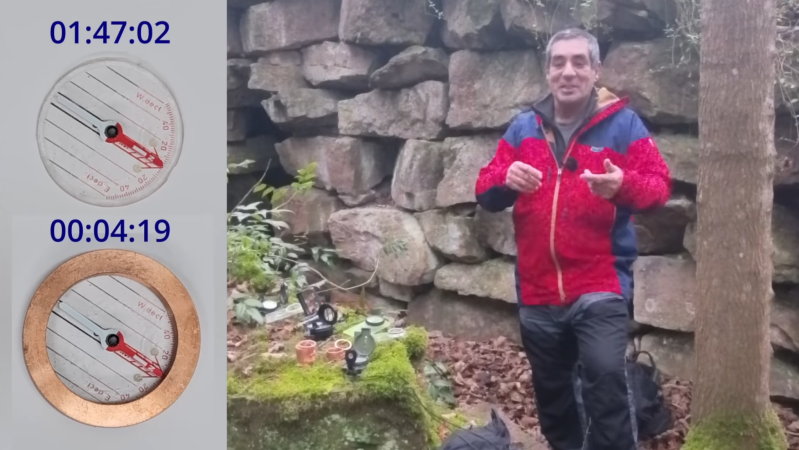
Leaving aside whether this is actually a new compass idea, the video demonstrating it is very sketchy. At the exact moment the novel compass slows down massively in the video around 12;19, there is a complete shift in lighting between timestamp 00:00:19 and 00:00:20, indicating that there are two videos that were sliced together. Youtube Comments that indicate this including mine have been removed entirely.
Johathan MB, concerning observation, especially given how much credibility hinges on transparent demonstrations.
It’s a pretty neat implementation anyway, regardless of absolute originality or not. And as far as I recall, I haven’t seen a baseplate compass (or geo compass) that uses a ring, though I’m more knowledgeable on geo compassez anyway. The Breithaupt-Kassel COCLA do this in a way similar to brunton, that is, a conductive pan surrounding the magnet. It has a transparent bottom, though, outside of the central circle where the pan is.
It’s made for reading the dip direction from the bottom of the compass, though, not for laying on top of maps, but I guess that could work as well? Having said that, it’s a 1000+ euro compass, so a cheaper compass with good magnetic arrest is still a good idea.
Having said that, on the note of compass bubles… I personally like them. They turn into a way of using a cheap compass as a clinometer for measurements, and Silva’s matchbox compass explicitly uses this as far as I remember.
Why is nobody mentioning the fact that this is edited. if you go frame by frame you can clearly see the point at which the lower compas and the reflections change. i noticed it as soon as i watched the video because the needle doesnt slow down or overshoot at all.