Although the RTL-SDR is cheap, accessible, and capable enough for many projects, it does have some important limitations. In particular, its bandwidth is limited to about 3.2 MHz, and the price of SDRs tends to scale rapidly with bandwidth. [Anders Nielsen], however, is building a modular SDR with a target price of $50 USD, and has already reached a bandwidth of almost 20 MHz.
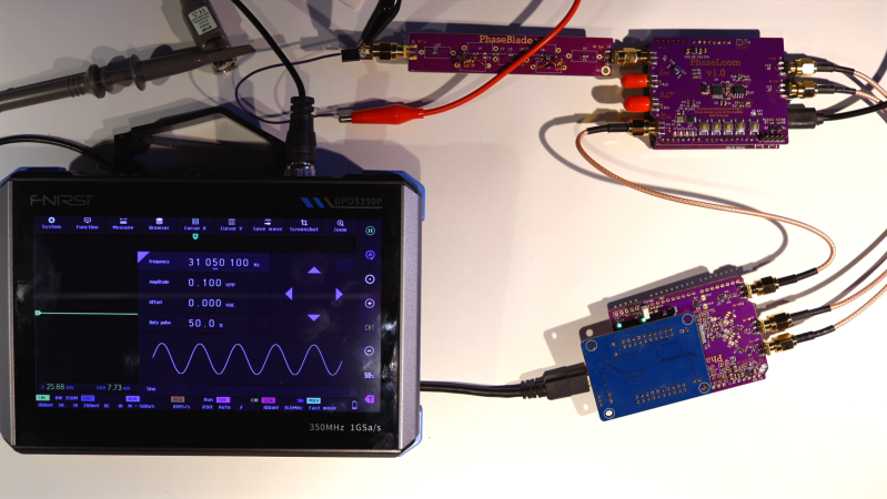
If this project looks familiar, it’s because we’ve covered an earlier iteration. At the time, [Anders] had built the PhaseLoom, which filters an incoming signal, mixes it down to baseband, and converts it to I/Q signals. The next stage is the PhaseLatch, a board housing a 20-MHz, 10-bit ADC, which samples the in-phase and quadrature signals and passes them on to a Cypress FX2LP microcontroller development board. [Anders] had previously connected the ADC to a 6502 microprocessor instead of the FX2LP, but this makes it a practical SDR. The FX2LP was a particularly good choice for this project because of its USB 2.0 interface, large buffers for streaming data, and parallel interface. It simply reads the data from the SDR and dumps it to the computer.
The FX2LP didn’t support the ADC’s clock rate, and overclocking the ADC led to issues, so [Anders] connected the ADC to an independent 20 MHz oscillator. The frequency spectrum of the SDR was oddly bell-shaped, which turned out to be due to the limited analogue bandwidth of the PhaseLoom (about 650 kHz) falling behind the digital bandwidth of 20 MHz. The PhaseLoom’s bandwidth seemed to be limited mostly by an amplifier, and decreasing its gain greatly improved matters. The SDR doesn’t yet have a 20 MHz bandwidth according to the normal definition, but it’s close enough to be practical, and further improvements will have to wait on an updated PhaseLoom board.
The Cypress development board used here is surprisingly capable – we’ve previously seen it used to build an SDR GPS decoder. Most of the custom-built SDRs we see don’t focus on technical performance, but do use such interesting components as a tube-based receiver or a custom silicon chip.


Weren’t the whole FX2 and FX2LP IC family discontinued recently?
They offer something new called “FX2G2”, but this is completely incompatible with any code written for the FX2, because it has an ARM core instead of the 8051 and looks like a stripped-down version of the FX3.
An FX3 would be a huge improvement to allow much higher bandwidth.
Except for Infineon’s pesky licensing issues, which are why sigrok STILL doesn’t support the FX3.
Well, that looks like a lot of fun.
I’m amazed that Cyprus part is still around. We used it in a high-speed USB ADC design from 2007: Parallel 14 bit ADCs running in bursts at an aggregate 2 GS/s, all funneling down the skinny 20 MS/s USB2 pipe through the Cyprus. It cost a heck of a lot more than $50 though.
Even if the ADC chip is fast, passing 20 MSps 10 bit x 2 (I/Q) ADC data through FX2 won’t happen. With its tiny buffer memory, it can barely manage to do 24 MB/s reliably.
If USB3 is not an option, some fast USB2 HS capable microcontroller could be used to apply a simple compression like ADPCM on the fly, and to provide enough buffer RAM to get around 40 MB/s through.
The capabilities are not misrepresented in the actual project though, it’s just hackaday summary that claims more than what is actually there.
If properly driven, the FX2 can manage about 41 MiB/s reliably, I have tested that myself:
https://github.com/GlasgowEmbedded/glasgow/issues/220#issuecomment-752655318
But this is USB. It relies completely on having full buffers available at the right moment and keeping up refilling those buffers. The 8051 in the FX2 is by no means able to convert some arbitrary ADC protocol and use that to fill the buffers. The protocol must match what the FX2 hardware expects or you need some small FPGA or similar to convert.
I’ve achieved consistent >24MBps rates with a fx2 and libusb before (running for over an hour). It just requires maintaining enough inflight bulk read requests to to cover your worst case latency.
Its fairly easy to do > 24MByte/s on average, but not consistently.
The FX2 has quad-buffering with 512 byte buffers. Depending on the Host Controller schedule, these buffers will be drained, the FX2 NAKs, the controller goes to idle, and will do the next poll only with the next microframe. Unfortunately, if you fill the buffers synchronously, without any additional buffer, you will then have an buffer overrun in the FX2. Some controllers will poll again in the same microframe after receiving a NAK, some wont, some insert a pause.
There are just two possibilities to get reliable transfer rate with the FX2:
– use less than 1.5 kByte per microframe (i.e. 12kBit * 8000 /s ~= 100 Mbit/s)
– have an additional buffer of at least 8 kByte, and feed that with preferable 16 bit * 48 MHz into the FX2 whenever there is space
Sipeed uses the smallest GW5AT FPGA in their SLogic16u3 logic analyzer to sample 16 bits at 200 MHz over USB 3. Buying them is single quantities is where it gets difficult.
Sounds like a decent FPGA would fit nicely into this project!
I’ll make my shameful plug: https://hackaday.io/project/205055-crystal-board-fpga-platform-for-all