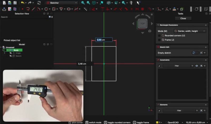
It’s a common ritual: whipping out those calipers or similar measuring devices to measure part of a physical object that we’re trying to transfer into a digital model in an application like FreeCAD. Wouldn’t it be nice if said measurements were to be transferred instantaneously into the model’s sketch, including appropriate units of measurement? That’s essentially what [stv0g] has done by merging a Sylvac Bluetooth-enabled caliper and FreeCAD using a plugin.
Key to the whole operation is a Bluetooth-enabled caliper like the Sylvac S_Cal EVO that [stv0g] managed to score on EBay for a mere €90 when it normally goes for multiple times that amount. This has BLE built in, using BLE’s standard GATT profiles for device communications specifications. Along with the provided Sylvac developer tools, this made it relatively easy to develop the InstrumentInput addon for FreeCAD.
This addon can be easily installed via FreeCAD’s addon manager as well, or if you wish to just use the calipers this way and don’t care about FreeCAD, the base Python library is also available.
Interestingly, this BLE-enabled caliper also supports HID mode, to emulate keyboard input, and thus it can work in any application by default. The reason why [stv0g] didn’t use this was that it only sends data when you press the caliper’s button, and it’s rather slow and limited.
Ever wonder what’s inside those calipers? We did too.


wild to try to imagine the workflow where this actually makes sense
Never reverse engineered anything before, eh?
I do it a few times a year. I’ve tried a few different workflows but lately… I hold the thing in my hands and i draw a poor diagram on a piece of paper. And i illustrate that diagram with the measurements that i think i’ll need…usually about a dozen. Then i set down the object and take the paper to my laptop and draft it in openscad. And inevitably, i’ve forgotten a couple measurements so i fudge them and then go back and measure them.
Sometimes, i do it backwards…i draft it in openscad with all fudged measurements and then i go back and measure from the thing, once i know what i will need.
There’s a bunch of steps in that that are kind of time consuming. Deciding which measurements i need is big, and it’s related to the task of deciding which primitives (cylinder cube etc) i want to use. I am very interested in naming the geometry, naming the measurements and naming the intermediate objects. Just picking good names can take a moment but is always rewarded. Closely related is picking the object hierarchy.
Compared to all that, the task of typing a dozen numbers into the computer simply doesn’t take any time at all. I’d have to do a much larger volume of objects and i’d have to get really good at all of the other tasks, before the volume of measurements would reach the level where saving the typing step is even measurable. Really, the biggest inconvenience i have with measuring is that i have to get out of my chair and go grab my calipers and then carry them to a third location. Probably only half the times is the object that i’m measuring able to sit on my workbench.
I get the impression ‘freescad’ users might not be as careful with naming and object hierarchies and so on — but i know that’s not free of downsides for them because “topological naming problem” had to be described. But still, it’d take a pretty radical departure from my workflow in order for such a doodad to be useful. So it’s hard to relate to, and fun to imagine.
Based on how FreeCAD starts sketches now, I think this would be really useful if you have it set up to do a multi segment line. The workflow is well suited to an input mechanism like this. It’s not how I model things, but since FC1.0 there’s definitely a reason to rearrange my workflow and this would work quite well that way.
Doesn’t seem that wild to me, any time you are working to an existing object automatic transposition into the sketch of the real world measurements is about as close as you can get to those really spiffy 3d point cloud type measuring arms that let you trace all the important features of the real object with the reliability and precision the 3d scanners really can’t match.. On a comparatively low budget compared to those alternatives too, as even at sticker price a Bluetooth caliper isn’t that costly.
Maybe for you. My daily bread.
Imagining using this sort of thing where you are designing a part to interact with something you’ve got on the bench and eyeballing imaginary interfaces with the calipers.
This is actually brilliant.
Many times over I wish I’d had a dial wheel (or like four, six, etc) directly tied to a setting/settings inside Solid Works, similarly how keyboard players have MIDI control “keyboards”, dials, faders, pushbuttons, etc. Equalizer faders if you must, ye, tho assigning these by hand is the worst part, in some cases I’d rather they themselves figured out which parameter/parameters to attach themselves to for the manual tweaking.
Maybe add an IMU and let a program (3D CAD???) construct vague/approximate model.
Some buttons to select what you’re measuring (radius, diameter, outer/inner length, …).
Add a stereo/3D camera with object detection into the game and it could potentially be almost fully automated (with some machine learning).
That’s a thought, thank you for sharing.
It is pretty clever to see someone finally bridge the gap between physical measurements and CAD software like this. Usually, you’re stuck manually typing in every single dimension from your calipers, which is exactly where most mistakes happen when you’re modeling a complex part.
Using the Bluetooth output to feed those numbers directly into FreeCAD’s Python console is one of those “why didn’t I do this sooner” ideas. It turns a tedious measuring task into something that feels way more fluid, and it’s a great reminder of why open-source tools are so valuable—you can just write a script to make your hardware talk to your software exactly how you want.
The next iteration is to use the data connector of a cheap caliper along with an nrf52840 with a small x,y,z keypad, diameter, radius and a touch sheet that sends the measurement when the position is fixed.
i read that as “bluetooth clapper” — which someone should totally make, even though clapper is solving the exact same problem — info communication at a short distance — that bluetooth solves
I find that I tend to reverse engineer things that have been mass produced. These things tend to fall within tolerances, so you get 5.98mm on one thing and 3.4mm on some other thing, but if you consider the intention of the original design, we’re probably looking at a 6mm thing and a 3.5mm thing. Using the exact measured dimensions is typically not very useful. If I have to deal with the caliper inputting numbers automatically, I will then have to deal with changing those numbers to the value that my reproduction requires to get as close to the original intended dimension as possible. That might just be even more typing and editing than if I did it by hand and wrote or typed each measurement after taking it.
It looks and sounds nice, but I’m skeptical of the actual utility for reverse engineering. I think this would be more useful in a scientific setting where measuring a large number of variables under test is the goal. Those numbers don’t need tweaking since the actual variance is the target.
You don’t need to edit everything manually, and probably shouldn’t either. Better to keep the actual measurement untouched and parametrically shift the features to allow for that tollerance for each feature. Should be able to select all the features that matter and shrink/enlarge to fit with your tolerance variable, and if you are using this to set dimensions on a sketch you have fully constrained you probably only need to add your tolerance tweak to one, maybe two measurement points as all the rest will follow.
I feel like you have it backwards, as in, applying tolerances to dimensions.
He’s talking about removing the tolerances to get the intended dimensions. You are basically stripping off errors in manufacturing and your own measures to get what seems like was intended by the original designers.
In no way is it going to be consistent what magnitude, let alone direction, these need to be adjusted in. You’re going to be rounding up or down based on reason as you go.
The way FC1.0 works now is you draw a line, and it automatically pops up a window to ask you the length, and the way this seems to work is it auto populates that window. But at least with the way I have mine set up, you can type something into the window, and then retype it, and then retype it again or whatever, and until you hit another button it doesn’t actually get stored. So you could send the caliper dimensions, see that it says 3.498, and say oh well that actually needs to be 3.5, or just leave it and hit ok.
Not really tolerance in your part to mate well with the real world part, or to create a suitable drop in replacement for the part you are measuring is the point in most cases – doesn’t matter if that part was nominally “clearly” meant to be 3/16ths or 5mm if it isn’t – it might well not be on purpose as its actually that size after the required clearances have been applied – so maybe that nice round number is actually the mating surface it is meant to slide on! (etc).
So unless you have huge numbers of example to prove this one is just low/high end of tolerance centred around the number you want it to be…
1D scanning
Having learned to use a Vernier scale caliper some 50 years ago and having used one semi-daily since the 3D printer showed up, I’m quite comfortable doing it that way. It seems this though would be very welcome for more intense reverse designing. Also nice to see it available for FreeCAD, my CAD preference.