The problem with tube based audio is that it has so often been hijacked by people for whom the bragging rights of having a tube amplifier outweigh the benefits, or the sheer fun of building the thing. [Bettina Neumryr] makes a speciality of building projects featured in old electronics magazines, and her latest, a tube amplifier from 1955, is a fantastic antidote to the gold-plated silliness of audiophile tube amplifiers.
Design wise it’s relatively straightforward, with a preamplifier before a two-tube transformerless splitter circuit driving a push-pull output. She dives into the circuit a little, noting its feedback circuit to the cathode of the first splitter tube. There’s an accompanying power supply, a classic tube rectifier design that incorporates a hefty low-pass filter with a giant choke.
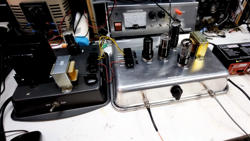
We particularly like her choice of chassis — while it’s possible to pay silly money for a tube chassis in 2026 she’s taken a much more down to earth approach with a pair of baking trays. We’re being honest here, they look surprisingly good. Component choices are limited by what’s available so most parts come from the junk box including the output transformer which causes her issues later. There’s a lot of mumbo-jumbo about tube amplifier layout, and she wisely sidesteps some of it.
The result after a few mishaps and a bit of unintended oscillation, is an amp which shows promise, but has distortion due to that transformer. We think she’ll have no problems sourcing a better one, which should bring that distortion figure into the acceptable range. You can watch the whole video below the break, and if that’s got you hooked, you can see one of our own youthful follies.


Classic construction method, neater than the other classic, building on a literal bread board.
I built my first tube amp 60 years ago on a cake pan. It cost a dollar, I think. These days I bend them up with a sheet metal brake. Good quality, aluminum cake pans have become pretty expensive.
Beautiful! Because all that metal-to-metal looks like a safety issue I assume it’s not. Any chance of explaining why not?
Metal to metal is a safety feature. As much as possible you want all the non-current carrying metal parts of equipment connected to each other and to the earth/ground of the supply. If any current carrying component were to touch metal it will just short to ground and hopefully blow a fuse before destroying some part of the circuit.
My qualm which I think you will understand comes from seeing electronics, particularly tube-based (higher voltage) electronics encased in Bakelite, plastic, or wood. More precisely, the baking tin looks like all the current carrying components are connected to it. I’m asking from ignorance here.
Its just kind of how they did things back in the day. There’s little to no saftey about it (other than being non combustible) add in the fact they would wires stuff directly onto it to act as a bus and non polarized plugs and they can will light your butt up!
Which is why the common wisdom is not to mess with them (and tv’s) unless you absolutely have your mind in the game
If done well (and beware, not all of them were), the chassis itself had its own ground lug. In the day before common grounded plugs, you ran this to your nearest metallic cold-water pipe and called it a day.
Any short or fault that could have become a hazard to the operator instead would become a blown fuse or a melted wire.
Safe, for definitions of safe. Certainly in comparison with the standards of the day for farm equipment ;)
Lol on typical construction like that you have a 50/50 chance of having a hot chassis thanks to non polarized plugs and ground lol what ground.
Ps: the only thing a fuse protects against is your failed circuit doesn’t start a fire… if something pops a fuse its already fked
The well-known “hot chassis” issue only exists with cheap, consumer-grade equipment that had transformerless power supplies which rectified the line current directly AND used the chassis for the negative return bud.the safety issues was overcome by mounting the equipment in insulated cabinets. To service the equipment when out of the chassis, we SMART radiomen powered the set through a 1:1 isolation transformer. The Scott Marine radio receiver by simply not using the chassis for the negative power bus.
Edit: The transformerless Scott Marine Receiver avoided this issue by simply NOT using the chassis for the negative power bus.
The only thing this construction would be dinged on these days is that the tubes are exposed. Modern H&S practice wants a mesh screen or similar to protect people from the high voltages inside the tubes and on their bases. The tagstrip connector wouldn’t be favored, either — it was common practice to incorporate the power supply into the amplifier.
I have a component 60-70 year old component audio system (a Quad 2). Its safe enough if grounded (“optional!”) but it would never pass muster these days. The power amplifiers are still available today (from another company) but they include radically different connectors and a perforated metal box over the tubes. A modern version of the preamplifier and tuners would likely use semiconductors since it would just be too difficult to safely power the units from the power amplifiers, segregating high voltage from accessible signal level circuits and so on. (One ‘for instance’ is that the return for the tuners’ tube anode voltage is carried by the audio lead from the tuner to the preamplifier — disconnecting this RCA audio jack puts a couple of hundred volts onto the tuner.)
This type of construction was the standard of the day and is perfectly safe when housed in a cabinet, which was also the standard of the day. When equipment was sold without a cabinet, the manufacturer expected the buyer to provide his own.
I’ve tried building a couple of tube amps from old magazines and the greatest challenge was finding capacitors with axial leads!
Anyway, if you’re looking for a design that uses a relatively low voltage, the “Valve Headphone Amplifier” by B. Kainka in the 10/2003 edition of Elektor works great. But give the original power supply a pass and buy a modern switching PS.
High voltages are relatively safe provided you take precautions. One important rule, for example, is that you never reach into a piece of equipment using both hands because you don’t want to run the risk of current flowing from arm to arm and damaging the heart. Obviously to further improve your survival chances you shouldn’t be standing on readily conductive surfaces and you never grab anything you’re not 100% sure is dead — I always experiment with the back of a finger first even if the equipment is off (because if I do get shocked the finger will curl away from the voltage source). Also, remember that the danger of electric shock isn’t just the shock, its the reaction that may well injure you or someone close by.
I grew up with vacuum tubes so these habits are ingrained. It can look a bit silly when you’re working with low voltages (although if there’s significant current then that can also be dangerous) but at least the caution can be explained away as anti-static precautions.
BTW — Just because a piece of equipment is solid state doesn’t mean its all low voltage. The typical switching power supply is extremely dangerous. Fortunately most of them are totally enclosed.
I was taught the ‘electricians stance’.
Off hand behind your back (so you don’t forget) standing on primary foot (worst case, the current will run down one side of torso and not cross your heart).
Also decent shoes, no holes for current to find.
Also also: Welders are killers despite their relatively low voltage, people get far too casual with them. Die when they are soaked in sweat and roll a 0. Impossible to avoid welding in tight spots you can barely reach while exhausted. Nature of task.
Best bet is to always take a second look at your plan in ‘safety mode’, right before you start.
Procrastinate. Don’t do it while exhausted. Almost always a better way. Drink a beer and think about it. Sleep on it.
Had to get old to realize the value of procrastination in avoiding foot bullets.
Subconscious is much smarter, but low bandwidth.
Finally protect head, amazingly low voltages and currents can kill you if induced in brain. Small cuts break skin barrier.
Yep, I thought all this to my beginning computer servicing students back when CRT monitors were still a thing.
Alternate electrician’s safety measure: Hold a bottle of beer in your off hand.
Or a esd wristband connected to ground?
Did you try reversing the connections on the secondary of the output transformer? It sounds as though you were getting positive feedback, not negative. A good way to build an oscillator!
Love the idea of using the baking sheet as a chassis. Looks great and you can drill holes in the lips to mount it into a cabinet.
Did you try reversing the secondary connections on the output transformer? Positive feedback instead of negative feedback gives you an oscillator instead of an amplifier! No feedback at all increases the percentage distortion rather a lot.
First breadboard then breadpan the way to cook up tube design.
You know the other reason you see a protective ventilated cover over tubes? Because usually they’re hot. Blisters on your fingers hot, as often as not.
The other Other reason is, they’re fragile, and don’t respond well to being hit about their delicate glass envelopes. They weren’t cheap way back when and they sure aren’t cheap now, either.
Ok, OK, also shielding them from the electromagnetic environment somewhat isn’t the worst thing, either.
Besides, if you can find some funky hexagonal mesh stuff, you can pick up a bit of that retro future ST vibe
The 60 Hz hum problem could probably be minimized by moving around the filament wires until it gets better, or injecting a small amount of filament voltage into the signal path, or moving or shielding the signal path wires, etc.. Another possibility is that there’s ripple in the B+ supply, which could be improved with a bigger capacitor. (That’s not likely since that would be 120 Hz.) She did twist together the filament wires, which is good practice.
Interesting to see the squegging waveform.
The resistance of the transformer windings is not a good indication of the impedance transformation the transformer should perform. Feed an AC signal through the transformer and square the ratio Vin/Vout to get the intended ratio of input to output impedance. For good efficiency the DC resistance on the primary should be half or less than the plate resistance of the 6L6, and the secondary’s resistance should be half or less the load (speaker) impedance. Her chosen transformer appears to be adequate but not excellent; given that she didn’t really have much choice in the matter she did OK.
The second harmonic distortion could be improved by trimming the R10/R11 ratio. The RCA Receiving Tube Manual suggests that an amp like this should be capable of 2% distortion at 30 Watts, but that requires a 400 V plate supply, a separate 250 V screen grid supply, and a perfect transformer.
Nice project well done.
A common source of mains hum was the ground loop where you had duplicate ground paths for signal and power. Internally it was common practice to not ground everything locally on the chassis but wire all ground connections to a single ground point that was the single connection to the chassis. (Not a daisy chain, note — everything’s a star connection.)
This was what caused the problem I mentioned in an earlier post where the B- was carried on the screen of a separate audio cable. This meant you could power a tuner up without the signal lead connected which would lead to a live unit. The problem was that any alternative would lead to potential hum or instability problems — providing an explicit B- (ground) connection would cause a ground loop and any attempt to isolate the audio signal screen would lead to potential induction or instability problems (its the fundamental problem with tubes — their high input impedance which made them sensitive to induced signals).
(Learning about, tracking down and dealing with stray paths was actually good training for modern layout design. These issues are still relevant and can be very time consuming to deal with because they show up as subtle effects like crosstalk between digital signals. Ground planes can also be very tricky and as for R/F — that’s where everything becomes an art form!)