It’s never been easier to get a printed circuit board made. In fact, almost every electronics video out on the internet will incessantly remind you of this fact now. But making a custom PCB wasn’t always as straightforward as sending a KiCad file to a board house. Many DIY methods involve harsh chemicals and tedious processes, but did have the potential benefit of taking much less time than waiting on boards to arrive in the mail. [Bettina Neumryr] is demonstrating one of these older methods, called the toner transfer method, using a circuit that was printed directly in an old magazine.
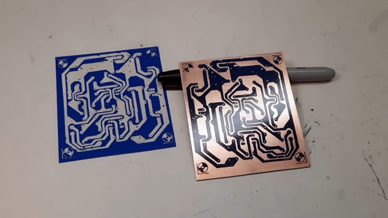
The first part of the toner transfer method is to create an image that can be printed. Since this circuit came from a magazine, it is first scanned in to a computer and imported into GIMP, where it can be scaled to match the size of the components and then sharpened to make a crisp print. With the image ready, it’s time to print the image onto some toner transfer paper, ensuring that the printer in question is a laser printer which actually uses toner. From there, a sheet of blank copper PCB is prepared and then the toner is transferred by heating, in this case using a laminator. After that its etched, removing all of the copper not protected by the toner, and then the toner itself can be removed which leaves behind the copper traces.
For those of you who were around when toner transfer was in vogue, this video might not have much value. But for anyone who can’t use a board manufacturer for whatever reason or is looking for alternatives, a modern video showing the method could be much more useful and have better context for beginners than videos made a decade or more ago now. Some of those older methods include similar processes using inkjet printers instead, but there are more modern DIY methods as well using lasers or CNC machines too.


There were times I wanted PCBs made in the 80s when I came across interesting stuff. Unfortunately scanner was expensive, laser printer was expensive, and I wasn’t allowed to have potentially toxic chemical before I became an adult. By the time I got back in electronics oh about 15 or 20 years ago, DIY was easy with free Eagle CAD and scanning from a magazine wasn’t really a thing anymore.
I still need to go back through all Popular Electronics and Radio Electronics magazines for the projects I still wanted, update it for modern components, and make my own PCB design.
I’m high school costs of laser printers and scanners were slowly dropping, but my school couldn’t justify them in the budget. So our electronics class went with the next best thing, sharpie and a ruler.
In university I designed a 68000 processor board for in an ISA slot. It was based on a design that I found in a magazine (I think C’t magazine). I modified it with some extra useful things. I got a good grade for the project. But never got to actually build it.
I could still build it. But I don’t really want to work on a noisy 90’s computer with ISA slots anymore. :) So it’s a past station.
It’s amazing what noise we put up with in the 90’s. I still kept a P200 system with ISA slots for whatever project I might need it for, one day. But the fan is noisy, the harddisk is noisy. Even the keyboard is noisy. :)
I made my first FTDI FT232RL adapters using the toner transfer method. This was before you could get them for a few bucks online. I collected the glossy pages of catalogues to use them as toner transfer paper. Together with an old iron and iron III chloride, this was all I needed.
Later I switched to photosensitive PCBs and worked with developer and NaOH.
The adapter actually died last month :D
You beat me to it. I couldn’t afford that fancy transfer paper. I had to tear a page from an old magazine to use for transfer. And a clothes iron to do the transfer too.
Elektor magazine was once known for its excellent artwork for circuit boards.
Initially, they provided high-quality acrylic film masters. Later, the quality of the artwork declined when they switched to tracing paper, and eventually, they printed the designs directly onto standard magazine paper.
This deterioration coincided with the commercialization of their projects, the introduction of an expensive PCB service, and distribution through licensed partners.
The method described is pretty absurd. Bettina is wrong to a great degree.
Programs like Sprint-Layout are a better option; they allow artwork to be created digitally and modified—for instance, if a component needs to be substituted.
Betina’s process is great for her purpose: one-offs from magazine artwork. Mr Karlson makes his own double-sided boards very successfully with toner transfer and carefully selected slick advertising paper that’s free. Lots of great detailed tips in his explanations. In the early 70s when I doing this, all I could afford was covering the copper with masking tape, transferring the layout by tracing with carbon paper, and cutting it with a #1 Exacto knife. Tedious, but worked fine and the only cost was ferric chloride.
I seem to remember the management changed around the same time, which almost certainly had something to do with it.
Yep. I had had a subscription to Elektor for many years. I have all the magazines, back to the mid-70s. Then the quality of the content went off a cliff and I cancelled my sub.
Then they bought Circuit Cellar. And ruined it. So much so that I think Steve Ciarcia bought it back. It’s much better now. I reinstated my subscription last year, for 3 years paid up front. Sadly they recently decided to drop to six issues per year. I think it’s clear what the next step will be. Such a shame.
I miss so many print magazines now. ETI, EW+WW, Practical Electronics, Byte, EDN, PCW, etc. I still have all the magazines I ever bought, which is many bookshelves worth. They have been in the bin many times. Only to be retrieved in the middle of the night when I decided that they deserved a reprieve. I still pull random ones off the shelf pretty regularly. There’s so much theory that will always be relevant.
In high school (77-78) I and 2 friends built don’t Lancaster’s tv typewriter on a PCB.
The magazine has the board layout. The school had photo etch resist and an arc lamp. We got some surplus double sided PCB. Did it best to line up both sides. We were only a little off. Then had to drill all those holes.
They weren’t plated through, and we decided to use sockets. I think I soldered all those sockets on both sides. Really made a mess of the sockets, melting the plastic.
In the end it worked, but I am happy there are affordable PCB vendors these days.
I’ve wondered how 1970’s magazine art was made into a PCB. I have a few I’m going to make and considered limiting myself to old methods.
First have PCB material coated with photoresist – either purchased that way or coated yourself. — This is sensitized PCB.
Then make a copy of the magazine art onto litho film using a copy camera.
Then develop the film.
Then make a contact print onto a pre-sensitized PCB with UV light.
Then develop the PCB image.
Then etch it, drill it, tin it, etc.
That was my first “real” job, more decades ago than I care to remember.
Up until around 12 years ago, before I sold out and moved to the USA, we still routinely prototyped our own boards like that. Print onto mylar direct from CAD
Toner transfer is easier. Basically photocopy the magazine PCB, iron onto the blank copper PCB and then etch.
In the late 80’s and early 90’s I attended DeVry Institute of Technology and was working towards an electronic tech degree. They had two experiment boxes that you could buy depending on whether you were working towards an EE or an ET. The ET box had a power supply and some switches and other things. The EE box had all that and a signal generator. I bought the EE box and built that. The connections inside wanted 9 wires soldered to a transistor on the left side and the same arrangement on the right side. I thought this was too old school so I bought the Radio Shack board etching kit and made some nice little boards with 12 holes in each connecting the wires to the transistor leads. The results were almost but completeley horrible as the resistant was a special sharpie marker and depended entirely on your art skills. It worked though and I still have the tiny little hand drill for the boars holes. I can’t find any pictures of the two boxes :(
Elektor were the best for this.
I bought my dad a new fuser roller for his office copier because I thought I could use any old transparency sheet to image a PCB from a Radio Electronics issue.
I ran a business in highschool making mods for various game console controllers. All of the PCBs used either a 555 or 556 timer and made using toner transfer and my sisters film developing trays. Paid for my first electric guitar with the proceeds
Lessons learned from that time:
Ferric Chloride while a great etchant is unnecessarily expensive and difficult to refresh after it has been used many times. Heat can help speed up well used etchant, but it is generally more trouble than its worth.
Cupric Chloride solution made from hardware
store HCl (muriatic acid) and Hydrogen Peroxide (first aid grade) works superbly well and can be driven in reverse with an aquarium pump to keep the etchant working well, again heat will always help.
Presensitized copper clad generally gives the best results due to the uniformity and low thickness of the mask. Using a laser engraver to ablate the mask after leaving it to expose in the sun allowed me to reliably get 4mil tacks and 6mil spaces on single layer etches.
Tin plating is a life saver. MG chemicals electroless tim plating solution while stinky is a dream to work with.
Create a library footprint with a standard fiducial pattern that can be used to drill alignment pin holes to make registration between top and bottom masks easier. If you have a cnc with a high enough spindle speed to drive small drills those tooling holes are also useful for automating your drills. Drills with a diameter of 30mils on a 50mil to 100mil pitch are generally doable by hand with enough patience and proper annular ring aspect ratio.
Clear coat spray from the hardware store works well enough as a single use mask if you have good fume extraction.
Keep your package choices to SOIC and 0603 if possible. 0.8mm qfp and similar pitch qfn packages can be done with practice, but packages with thermal pads are almost always a no go unless you plan on making a stencil too. But since single sided layout is usually my first choice if I plan on etching a prototype, getting thermal pads to work well in the design is entirely dependent on the component pin out. Sometimes it will really help, but others it will be a nightmare.
Photo gloss paper for toner transfer is also a great option. Overhead transparencies work really well too. Toner transfer with an iron or a cheap laminator from walmart works. Be careful with an iron as you can smear the toner ruining the fidelity of the transfer.
Acetone to strip the toner.
Cheap toothbrushes for cleaning and scrubbing.
Use all polypropylene containers (look for PP marked in the recycling symbol)
Do your research on proper neutralization and disposal procedures for whatever etchant you choose. I like to fish and swim, don’t be the reason people can’t enjoy the outdoors.
I got to the stage of:
Toner transfer to 0.8mm copper clad FR4 and etch once for the tracks and pads. A temperature adjusted laminator takes 0.8mm no problem and gives perfect repeatable transfers
Toner transfer a second time on the copper side to mask the pads
Airbrush with glass paint which can stand heat and chemical/solvent
Strip toner masking with acetone
Tin with tinning solution
Do it all twice and glue them for a double sided 1.6mm standard board
Dremel drill press and secondhand carbide bits from local fab houses
Finally toner transfer a third time on the component side then spray with clear lacquer for silkscreen
Ended up being able to make quite good boards – time efficient? Hell no. But part of the point was learning the process and going through the effort – now a $3 PCB from china is better and easier of course. I wonder if folks who grew up with easy pro PCB availability like there is nowadays lack the appreciation of what really goes into the PCB manufacture…..or is it just history repeating and I lack appreciation of something I’ve always had like cheap lightbulbs.
Scanner and computer? Back in the day we were forced to use a copier and an iron to transfer it the copper clad. Designs often used through hole components only because you would end up with mirror images unless you had access to a fancy copier.
Every PCB layout I recall seeing in magazines was already mirrored, although I admit my experience is far from comprehensive in this area. Also, even though-hole wouldn’t save you from mirroring if DIP ICs are involved.
I started making my own circuit boards in the late 70’s. Dry Transfer, Ruby Lith, painted lacquer resist, Sharpies, India ink in a plotter, … I’ve tried them all at some point. About the only methods I haven’t tried (yet) are silk screening and direct milling traces on a CNC machine. A friend once made a hand-drawn board for me using a soft graphite pencil (4B, I think) as an etch resist. It was ugly and had to have a few traces repaired, but it worked. When toner transfer came along, I jumped right in. It took many tries to find a paper that would photocopy clearly, transfer smoothly, AND wash away easily before etching. I found some shiny clay-surfaced paper as scrap at a local print shop and used that for years until I discovered the blue transfer stuff. When I finally mastered the technique I was quite pleased, at least until I started assembling my first board. Many components didn’t line up correctly, mostly ICs and radial capacitors. I compared the measurements of my board to the original and discovered the copier I was using at work didn’t accurately reproduce the original image. So I grabbed a sheet of grid-ruled paper and copied it onto a transparency sheet so I could easily compare the two. The copy was too narrow one direction and too wide the other. Fortunately the copier had independent X & Y scaling, and after a bit of experimentation I determined I needed to scale the copy 107% one direction and 92% the other direction (I still remember those numbers). This worked well for years until the company bought a different copier and I had to do it all over again. The last toner-transfer boards I made were printed on an HP IIID I rescued from the scrap pile. When that machine gave up the ghost I started ordering boards online, but I still miss making them myself.
I once hand-drew a preamplifier circuit design (copied from a PCB layout in the then-excellent Electronics Australia magazine) using an etch-resist pen and etched the board myself. Hand-drilled all the holes. The 70s were fun times.
I did this exact procedure back in the early 90s. Used a copier that I tweaked for more developer current, tshirt press as heating platform, copper clad board.. and ferric chloride.. and a mini drill press when done. Of all things.. i drew the board patterns in…… Microsoft paint. Pixel by pixel.
Kinda glad I live in a time where obtaining custom PCBs isn’t such a messy affair any more. Kinda sad about it too, in a way.
Crap, we were just using copiers, and transferring the toner directly from the copy to the board. The tedious process is actually to scan, use GIMP, adjust things, print. For those who never used a copier you can adjust contrast and luminosity and that is just fine.
I presume folks have experimented with FDM printing a resist pattern onto the copper.
I’ve used the toner transfer method for years and still do. I love making old retro projects and I usually only make a one off, which is pointless to send to a board house, so I make my own. It’s a bit messy, but it works for what I want to do. Now I just have to perfect double sided boards.
photocopier was the go to back in the day having a copier engineer in the family was a help.
Toner transfer is not good. Use regular oh paper and put two together and tape on the och that youve sprayed with photo resist and use uv light to cure then wash with NaOH then you etch